Developing device and image forming apparatus including the same

a technology of developing device and image forming apparatus, which is applied in the direction of electrographic process apparatus, instruments, optics, etc., can solve the problems of unstable toner charge amount, image defect, and inability to obtain stable image density, so as to reduce image density and suppress uneven toner density

Inactive Publication Date: 2011-09-15
KYOCERA DOCUMENT SOLUTIONS INC
View PDF8 Cites 2 Cited by
  • Summary
  • Abstract
  • Description
  • Claims
  • Application Information

AI Technical Summary

Benefits of technology

[0016]An object of the present invention is to provide a developing device of a three-axis transport type which can effectively suppress unevenness in toner density and a decrease in image density due to insufficient stirring of a two-component developer or an off-balance of the developer, and an image forming apparatus including the same.

Problems solved by technology

However, on the other hand, the toner is charged by a charging roller with a layer thickness on the developing roller being regulated by an elastic regulating blade, and hence an additive to the toner adheres to the charging roller and lowers a charging ability thereof, which makes it difficult to maintain a toner charge amount with stability.
Further, the toner sometimes adheres to the regulating blade, resulting in non-uniform layer formation, which causes an image defect.
This raises a problem that a stable image density cannot be obtained.
In particular, in a case where an image having a high density in part such as a patch image is printed, it is likely to cause a phenomenon called development hysteresis in which a part exhibiting a low toner density occurs in the developer and the previous image appears as an after image (ghost).
Hence, in particular, a high-speed machine exhibiting a high speed of transporting a developer is liable to have the insufficient stirring therein, which causes malfunctions that the toner density (T / C) within the developer is partially lowered and that lowered flowability inhibits the developer from being passed to the developer supplying-transport portion.
Hence, an ability to scoop up the developer may become insufficient in a downstream side portion of the developer carrying member, thereby lowering the image density partially.
In addition, in a case where a toner density sensor and a developer discharge portion are located in the vicinity of a downstream side of the confluence at which the developer is merged, there is a fear that there may occur erroneous detection of the toner density or excessive discharging of the developer due to irregularity caused in the volume of the developer.

Method used


Image

  • Developing device and image forming apparatus including the same
  • Developing device and image forming apparatus including the same
  • Developing device and image forming apparatus including the same

Examples


first embodiment

[0072]Therefore, a distance by which the developer within the collecting-transport chamber 23 is transported after being merged into the developer within the supplying-transport chamber 22 up to the toner replenishing port 20c is longer than in the first embodiment in which the developer within the collecting-transport chamber 23 is merged into the developer within the supplying-transport chamber 22 only from the communication portion 27. As a result, the developer within the supplying-transport chamber 22 is replenished with the toner after being sufficiently stirred and made uniform, and hence it is possible to further stabilize the toner density within the developer.

[0073]Further, the developer is gradually returned to the supplying-transport chamber 22 from not only the communication portion 27 but also the wide-range region on the upstream side thereof, which facilitates the control of the developer amount within the supplying-transport chamber 22 and can improve stability of a...

second embodiment

[0075]FIGS. 9A and 9B are perspective views schematically illustrating other structural examples of the collecting-transport chamber of the developing device according to the FIG. 9A illustrates structure in which a plurality of opening portions 40 are provided in the partition wall 20b, and FIG. 9B illustrates structure in which the partition wall 20b is gradually lowered from an upstream side in the transporting direction of the developer toward the downstream side.

[0076]The width of the region through which the developer is returned from the collecting-transport chamber 23 to the supplying-transport chamber 22 and the returning amount of the developer can be adjusted by changing the shape, size, number, and layout of the opening portions 40 provided in the partition wall 20b in the case of the structure of FIG. 9A and by changing the inclination of a top surface of the partition wall 20b in the case of the structure of FIG. 9B.

[0077]Next described is a developing device accordin...

third embodiment

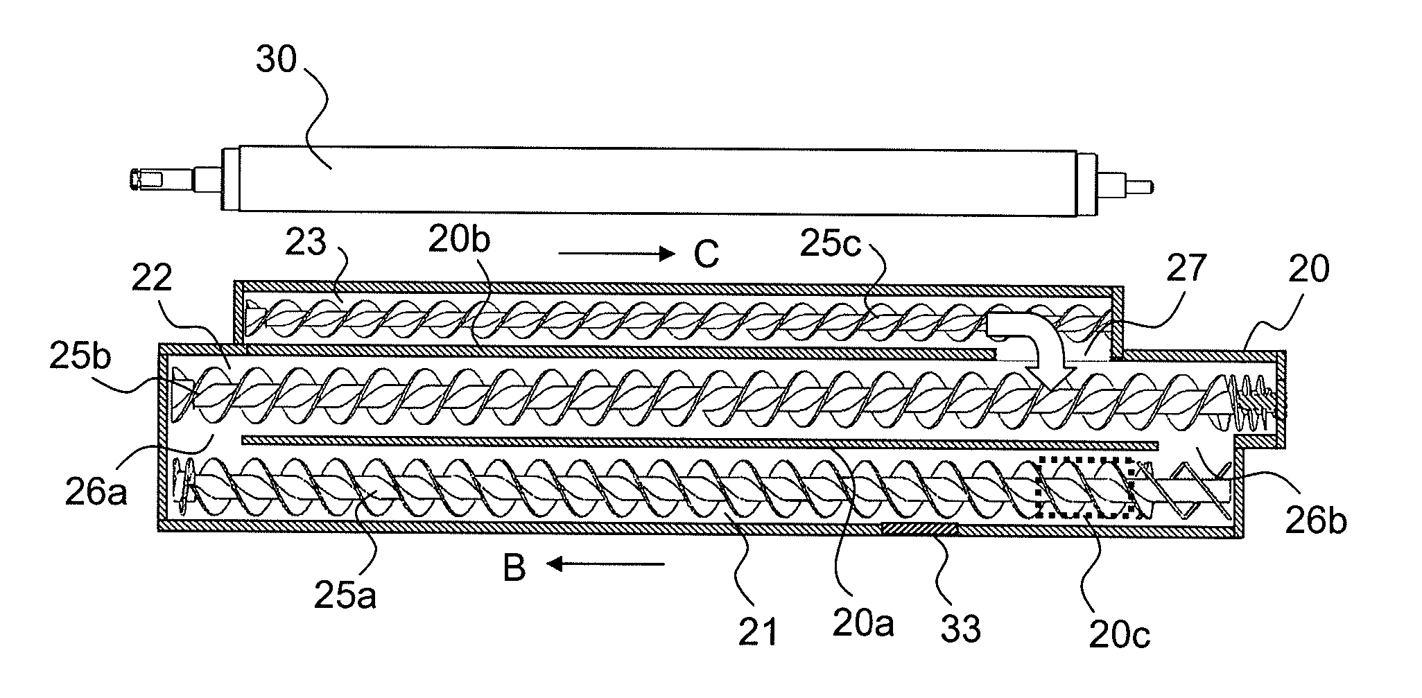
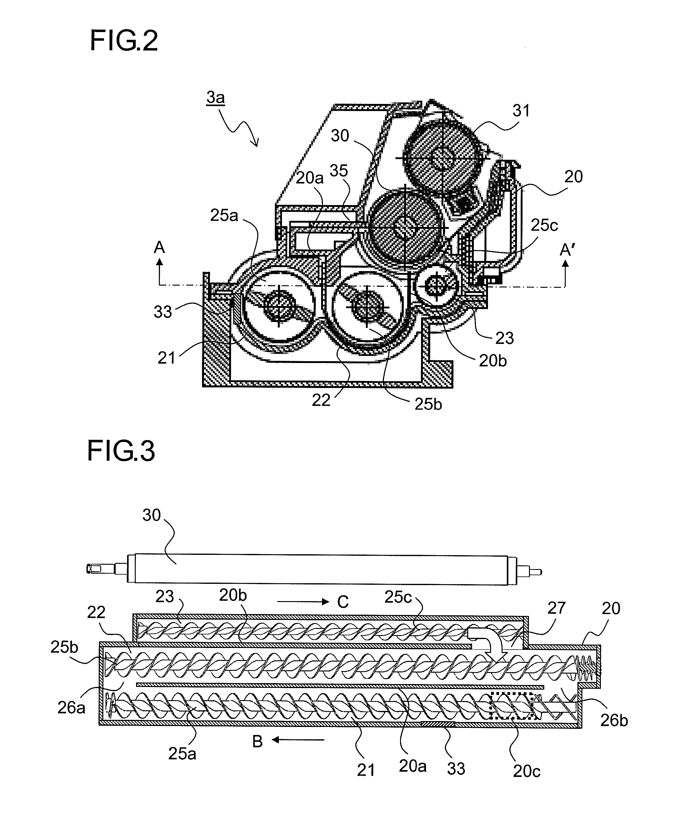
[0086]FIG. 12 is a sectional side view illustrating another structural example of the developing device according to the present invention, and FIG. 13 is a sectional plan view (sectional view from the arrows AA′ of FIG. 12) illustrating another structural example of the developing device. In FIG. 12, the transporting speed of the collecting-transport screw 25c is set slower than that of the supplying-transport screw 25b in the developing device of a two-component development method which is not provided with the developing roller 31 on which the toner thin layer is formed and performs the development by bringing the magnetic brush formed on the magnetic roller 30 into direct contact with the photosensitive drum 1a.

[0087]Further, as illustrated in FIG. 13, the communication portion 27 is provided in substantially the same position as the second developer passage 26b in terms of the transporting direction of the developer (direction indicated by the arrow C).

[0088]Also in the develo...


PUM


Abstract

Provided is a developing device including: a developing container partitioned into a stirring-transport chamber, a supplying-transport chamber, and a collecting-transport chamber that are arranged substantially in parallel with one another, for storing a two-component developer; a developer carrying member for carrying the developer on a surface thereof; a supplying-transport member located within the supplying-transport chamber; a stirring-transport member located within the stirring-transport chamber; a collecting-transport member located within the collecting-transport chamber, for stirring and transporting the developer in the same direction as the supplying-transport member and at the different speed from the supplying-transport member; a first developer passage for passing the developer from the stirring-transport chamber to the supplying-transport chamber; a second developer passage for passing the developer from the supplying-transport chamber to the stirring-transport chamber; and a communication portion for passing the developer from the collecting-transport chamber to the supplying-transport chamber.

Description

[0001]This application is based upon and claims the benefit of priority from the corresponding Japanese Patent Application No. 2010-57363 filed on Mar. 15, 2010 and Japanese Patent Application No. 2010-57366 filed on Mar. 15, 2010, the entire contents of which are incorporated herein by reference.BACKGROUND OF THE INVENTION[0002]1. Field of the Invention[0003]The present invention relates to a developing device mounted to an image forming apparatus such as a copier, a facsimile machine, or a printer and an image forming apparatus including the same, and more particularly, to a developing device which uses a two-component developer made of a magnetic carrier and toner.[0004]2. Description of Related Art[0005]Up to now, as development methods using dry toner which are employed in an image forming apparatus using an electrophotographic process, there are known: a one-component development method which does not use a carrier; and a two-component development method in which a two-compone...

Claims


Application Information

Patent Timeline
Patent Type & Authority Applications(United States)
IPC IPC(8): G03G15/08
CPCG03G15/0832G03G2215/0802G03G15/0855G03G15/0893G03G15/0865G03G2215/0827
Inventor KUBO, NORIOMORI, YUKIHIROSASAKI, ASAMI
Owner KYOCERA DOCUMENT SOLUTIONS INC
Why Eureka
Try Eureka