Piezoelectric device

Inactive Publication Date: 2010-11-04
MURATA MFG CO LTD
View PDF1 Cites 7 Cited by
  • Summary
  • Abstract
  • Description
  • Claims
  • Application Information

AI Technical Summary

Benefits of technology

[0039]According to various preferred embodiments of the present invention, it is possible to improve temperature cha

Problems solved by technology

In particular, in the case in which molding is performed with a resin, the cover layer 130 easily sags under pressure durin

Method used


Image

  • Piezoelectric device
  • Piezoelectric device
  • Piezoelectric device

Examples


Example

[0049]Preferred embodiments of the present invention will be described below with reference to FIGS. 1 to 5.

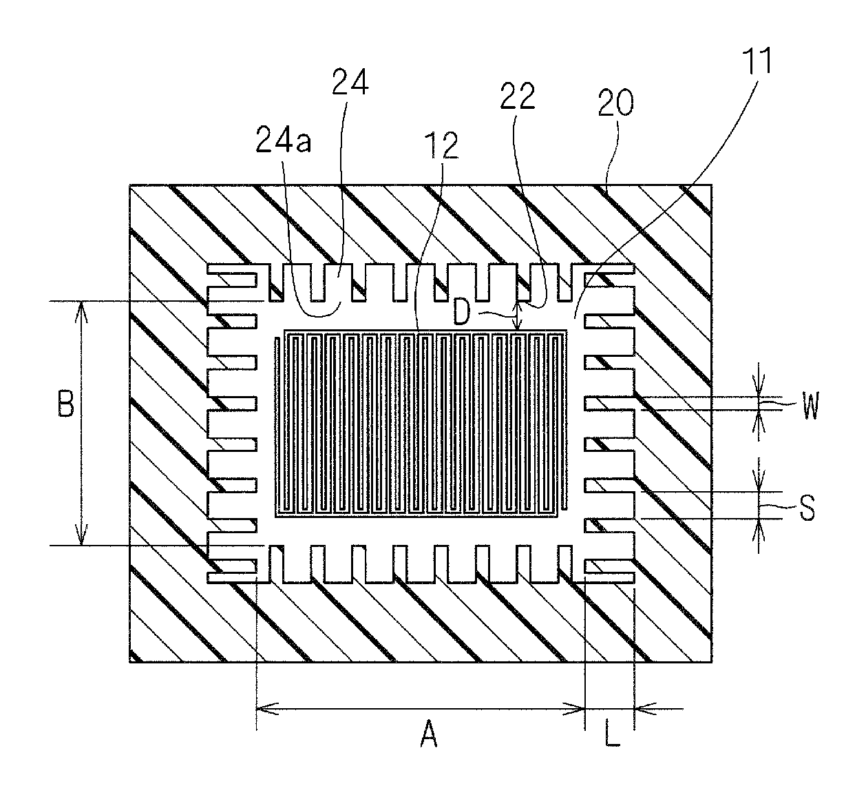
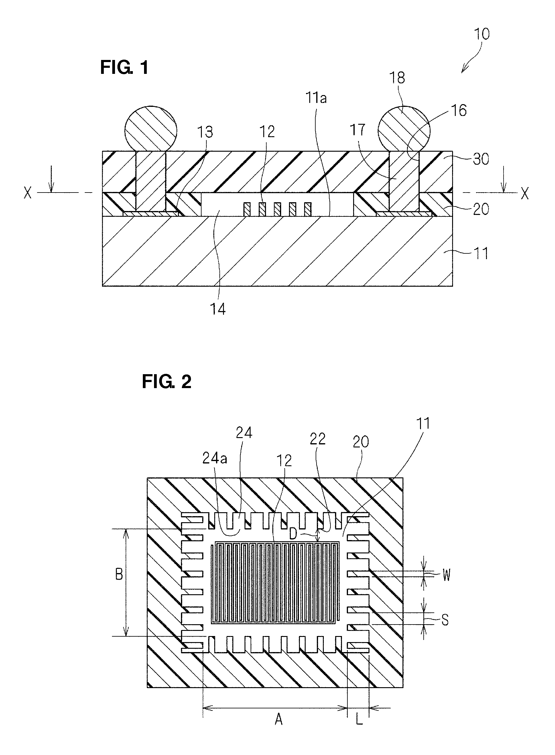
[0050]FIG. 1 is a cross-sectional view of a piezoelectric device 10. As shown in FIG. 1, the piezoelectric device 10 is a surface acoustic wave (SAW) filter in which an element portion is disposed on a piezoelectric substrate 11. An upper surface 11a, which is one main surface of the piezoelectric substrate 11, is provided with a conductive pattern including an interdigital transducer (IDT) electrode 12, which is a comb-shaped electrode, pad electrodes 13, and wiring (not shown) extending between the IDT electrode 12 and the pad electrodes 13. A supporting layer is arranged in a frame shape in the periphery of an IDT-forming region in which the IDT electrode 12 is provided. The thickness of the supporting layer 20 is greater than the thickness of the conductive pattern, such as the IDT electrode 12. The supporting layer 20 is also disposed on the pad electrodes 13.

[0051]A cove...


PUM


Abstract

A piezoelectric device includes a piezoelectric substrate, a conductive pattern which is provided on one main surface of the piezoelectric substrate and which includes an IDT electrode, a supporting layer which is arranged on the one main surface of the piezoelectric substrate so as to surround the periphery of an IDT-forming region in which the IDT electrode is provided and which has a thickness greater than that of the IDT electrode, and a cover layer which is arranged on the supporting layer and which covers the IDT-forming region. The supporting layer includes removed sections provided at a plurality of positions at least in a region close to the IDT-forming region, the removed sections being obtained by partially removing a portion of the supporting layer to be bonded to the one main surface of the piezoelectric substrate.

Description

BACKGROUND OF THE INVENTION[0001]1. Field of the Invention[0002]The present invention relates to a piezoelectric device, and more particularly, to a piezoelectric device in which an element portion, such as a resonator or a filter, is disposed on a piezoelectric substrate.[0003]2. Description of the Related Art[0004]A piezoelectric device has been proposed in which in which an IDT electrode disposed on a piezoelectric substrate is covered with a cover layer.[0005]For example, in a piezoelectric device 110 shown in a cross-sectional view in FIG. 8, on one main surface 111a of a piezoelectric substrate 111 having a conductive pattern including an IDT electrode 112, and pad electrodes 113, a frame-like supporting layer 120 made of a resin is arranged so as to surround an IDT-forming region where an IDT electrode 112 is arranged, and a cover layer 130 made of a resin is disposed on the supporting layer 120. Furthermore, the piezoelectric device 110 is entirely covered with an outer resi...

Claims


Application Information

Patent Timeline
IPC IPC(8): H01L41/053H01L41/047
CPCH03H9/1092H03H9/059H01L24/03H01L2224/05001H01L2224/05022H01L2224/05644H01L2224/05655H01L2224/13H01L2924/00014
Inventor KUDO, HAYAMITAKAMINE, YUICHIIKADA, KATSUHIRO
Owner MURATA MFG CO LTD
Why Eureka
Try Eureka