Vibration sensor

Inactive Publication Date: 2007-12-06
FUJITSU MEDIA DEVICES +1
View PDF7 Cites 2 Cited by
  • Summary
  • Abstract
  • Description
  • Claims
  • Application Information

AI Technical Summary

Benefits of technology

[0006] The present invention has been made in view of the above circumstances and pro

Problems solved by technology

However, the diffused resistors may have a difficulty in realizing stable temperature characteristics of resistance in mass production.
Further, the diffused resistors designed to have temperature characteristics leads to a situation in which the differential amplifier itself has a temperature characteristic.
It is therefore difficult to reliably compensate for the temperature characteristic of the sensitivity.

Method used


Image

  • Vibration sensor
  • Vibration sensor
  • Vibration sensor

Examples


first embodiment

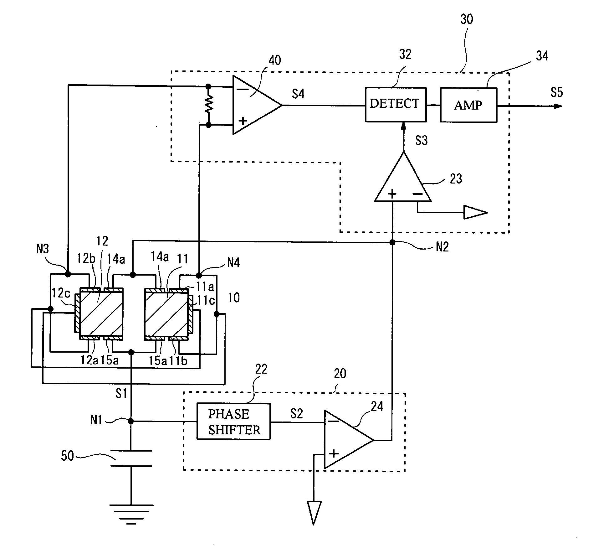
[0025] A first embodiment is an exemplary angular velocity sensor having a tuning-fork type vibrator as a vibration body. FIG. 3 is a block diagram of a sensing system in accordance with the first embodiment. The sensing system includes a vibration body 10 (tuning-fork type vibrator), a drive circuit 20 and a sense circuit 30. Drive electrodes 15a of the vibration body_10 are grounded via a capacitor 50. The drive circuit 20 is connected to a node N1 between the drive electrodes 15a and the capacitor 50. The capacitor 50 is connected between the drive circuit 20 and ground. The drive circuit 20 includes a phase shifter 22, and a phase inversion amplifier 24. The phase shifter 22 delays the phase by 90 degrees to change the phase of a drive signal S1 and produce a resultant signal S2. The phase inversion amplifier 24 inverts the phase of the output signal S2. The output signal of the drive circuit 20 is applied to drive electrodes 14a of the vibration body 10. Sense electrodes 12a, 1...

second embodiment

[0038] A second embodiment is an exemplary vibration sensor in which the sensitivity of the sense signal can be compensated for using the temperature characteristic of the phase of the aforementioned phase shifter 22. Parts (a) through (d) of FIG. 12 show a case where the phase of the reference signal S3 changes while the phase of the sense signal S4 does not change. Part (a) of FIG. 12 shows the reference signal S3. When the reference signal S3 has a phase S32, the reference signal S3 is in phase with the sense signal S4, and the output signal S5 is the maximum as shown in part (c) of FIG. 12. The phase different at that time is the reference phase difference. When the reference signal S3 has a phase S31, the phase of the reference signal S3 leads to the sense signal S4. When the reference signal S3 has a phase S33, the phase of the reference signal S3 lags behind the sense signal S4. Thus, when the reference signal S3 has the phase S31 or S33, the output signal S5 is reduced as in...


PUM


Abstract

A vibration sensor includes a vibration body, a drive circuit that vibrates the vibration body, a sense circuit that refers to a reference signal associated with a drive signal for the drive circuit and detects a physical state of the vibration body on the basis of a sense signal related to vibration of the vibration body, and a capacitor provided between the drive circuit and ground. The capacitor has a temperature characteristic of a capacitance value defined so as to compensate for at least a part of the temperature characteristic of a sensitivity of the sense signal to the vibration of the vibration body.

Description

BACKGROUND OF THE INVENTION [0001] 1. Field of the Invention [0002] The present invention relates to vibration sensors, and more particularly, to a vibration sensor having a function of compensating for temperature characteristics of sensitivity. [0003] 2. Description of the Related Art [0004] Vibration sensors such as acceleration sensors and angular velocity sensors have a vibration body. Vibrations of vibration body are sensed to thus detect acceleration and angular velocity. For example, the angular velocity sensors are used for car navigation systems and image stabilization in digital cameras. The vibration body of the vibration sensors is formed by a piezoelectric material, which converts vibrations of the vibration body into an electric signal. However, variations in the atmosphere change the sensitivity of the sense signal in converting the mechanical vibration into the electric signal. FIG. 1 is a graph of the sensitivity of an angular velocity sensor as a function of tempe...

Claims


Application Information

Patent Timeline
IPC IPC(8): G01H11/06G01C19/56G01C19/5614G01P1/04G01P15/125
CPCG01H11/08G01C19/56
Inventor TAKAHASHI, YUJINAKAZAWA, FUMIHIKOISHIKAWA, HIROSHIYACHI, MASANORIYAMAJI, TAKAYUKIOHTA, MINORU
Owner FUJITSU MEDIA DEVICES
Why Eureka
Try Eureka