Multi-Pattern Wireless Frame Transmission

a wireless frame and multi-pattern technology, applied in the direction of electrical equipment, power management, antennas, etc., can solve the problems of interference, interference can not occur, and the possibility of interference arises,

Active Publication Date: 2010-11-04
HEWLETT-PACKARD ENTERPRISE DEV LP
View PDF4 Cites 34 Cited by
  • Summary
  • Abstract
  • Description
  • Claims
  • Application Information

AI Technical Summary

Problems solved by technology

When devices operate in close proximity, both in terms of physical location and radio frequencies, opportunities for interference arise.
Such interference can occur not only when devices operate on the same channel, but when devices operate on partially overlapping or adjacent channels.
Channels 1 and 6 are adjacent, but they can still interfere with each other depending on the proximity of the devices and strength of transmissions.

Method used


Image

  • Multi-Pattern Wireless Frame Transmission
  • Multi-Pattern Wireless Frame Transmission
  • Multi-Pattern Wireless Frame Transmission

Examples


second embodiment

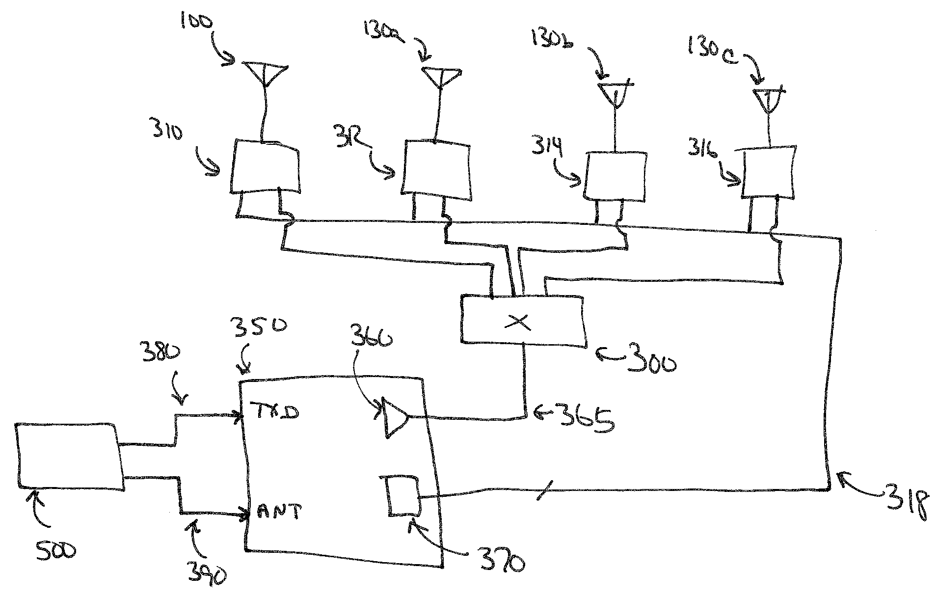
[0028]According to the invention, a second embodiment is shown in FIG. 4. Where transmitter 350 of FIG. 3 generates antenna switching signals 318 directly, and thus must be designed and implemented in accordance with the invention, the embodiment of FIG. 4 uses an unmodified transmitter 350 and implements antenna switching along side the transmitter. This embodiment may be more applicable for use with standard designs and / or prebuilt transmitter and transmitter / receiver assemblies. Antenna selection 318 is provided by antenna controller 400 which receives antenna data 410 from controller 500. In such an embodiment, antenna pattern switching is timing based. When a multi-pattern frame is to be transmitted, controller 500 sends to antenna controller 400 information on which antenna pattern is to be enabled for the first period, the time of the first period, and information on which antenna pattern is to be used for the second period.

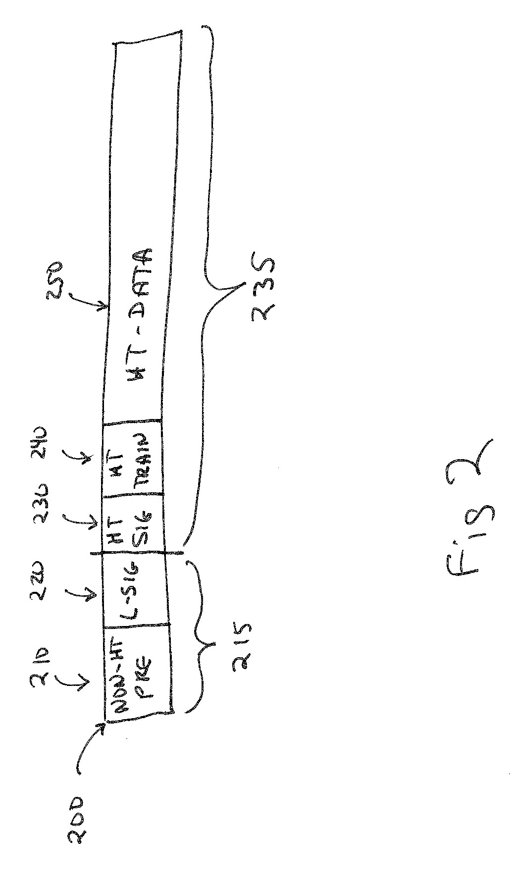
[0029]As an example, using a frame 200 such as shown...

first embodiment

[0030]As with the embodiments of FIG. 3, in FIG. 4 when transmitting a multi-pattern frame 200, controller 500 commands antenna controller 400 to select switch 310 and antenna 100 for the first portion of the frame, for example, broadcast portion 215 of FIG. 2. Controller 500 also sends antenna controller 400 the duration of the first portion of the frame, and the antenna to select when this portion is complete. Controller 500 then signals the start of the transmission, sending data 380 to transmitter 350. When the counter in antenna controller 400 expires, it switches off switch 310 and antenna 100 and switches on one of switches 312, 314, 316 and accompanying antenna 130a, 130b, 130c.

[0031]In an alternate embodiment, when transmitting a multi-pattern frame 200, controller 500 commands antenna controller 400 to select switch 310 with antenna 100, and one of switches 312, 314, 316 and accompanying antenna 130a, 130b, 130c. Controller 500 also sends antenna controller 400 the durati...


PUM


Abstract

Multi-pattern transmission of wireless frames. A digital device contains a transmitter feeding an electronically steerable antenna system where the radiation pattern produced by the antenna system may be selected. Different antenna radiation patterns are used in transmitting a first portion of a wireless frame and a second portion of a wireless frame in a wireless digital network. In one embodiment, a first portion of a wireless frame is transmitted using a wide radiation pattern while the second portion of the frame is transmitted using a second radiation pattern. Switching among radiation patterns in the electronically steerable antenna system may be accomplished by switching between antenna types, such as an omnidirectional antenna for the wide pattern, and beam-steered or sectorized antennas for the second radiation pattern. Beam-forming and / or phasing approaches may also be used. The first and second portions of the frame may be transmitted at different power levels. For high throughput (HT) frames such as IEEE 802.11n frames, the non-HT preamble and L-Sig are taken as the first portion of the frame, with the HT-Sig, HT-training and HT-data portions of the frame taken as the second portion of the frame, transmitted using a narrower radiation pattern.

Description

BACKGROUND OF THE INVENTION[0001]The present invention relates to wireless digital networks, and in particular, to the problem of transmitting information in dense or crowded RF environments and improving the reliability of transmissions in any environment.[0002]Wireless digital networks, such as those operating to IEEE802.11 Ethernet standards, use wireless access nodes connected to controllers and provide a wide range of services to wireless clients, such as access to infrastructure devices and services such as printers and file servers, as well as to the greater Internet. In RF-dense environments like those found in corporate offices, it is common to have many devices, wireless access nodes and wireless clients both, operating in close proximity.[0003]When devices operate in close proximity, both in terms of physical location and radio frequencies, opportunities for interference arise. Such interference can occur not only when devices operate on the same channel, but when devices...

Claims


Application Information

Patent Timeline
Patent Type & Authority Applications(United States)
IPC IPC(8): H04B7/00
CPCH04B7/0408H04W52/42H04W52/322
Inventor PONNUSWAMY, SUBBURAJAN
Owner HEWLETT-PACKARD ENTERPRISE DEV LP
Why Eureka
Try Eureka