Boost Device For Voltage Boosting

a boost device and voltage technology, applied in the direction of dc-dc conversion, power conversion systems, instruments, etc., can solve the problems of damage to the conventional boost device, the boost device cannot provide electrical isolation, etc., and achieve the effect of boosting the voltag

Active Publication Date: 2010-11-04
HUNGKUANG UNIV
View PDF7 Cites 23 Cited by
  • Summary
  • Abstract
  • Description
  • Claims
  • Application Information

AI Technical Summary

Benefits of technology

[0013]a boost circuit coupled to the anode of the output diode and the second terminal of the output capacitor, and across the second winding of the transformer, the boost circuit being capable of...

Problems solved by technology

However, such a conventional boost device cannot provide electrical isolation.
Thus, for an outdoor power supplying ...

Method used


Image

  • Boost Device For Voltage Boosting
  • Boost Device For Voltage Boosting
  • Boost Device For Voltage Boosting

Examples


Embodiment Construction

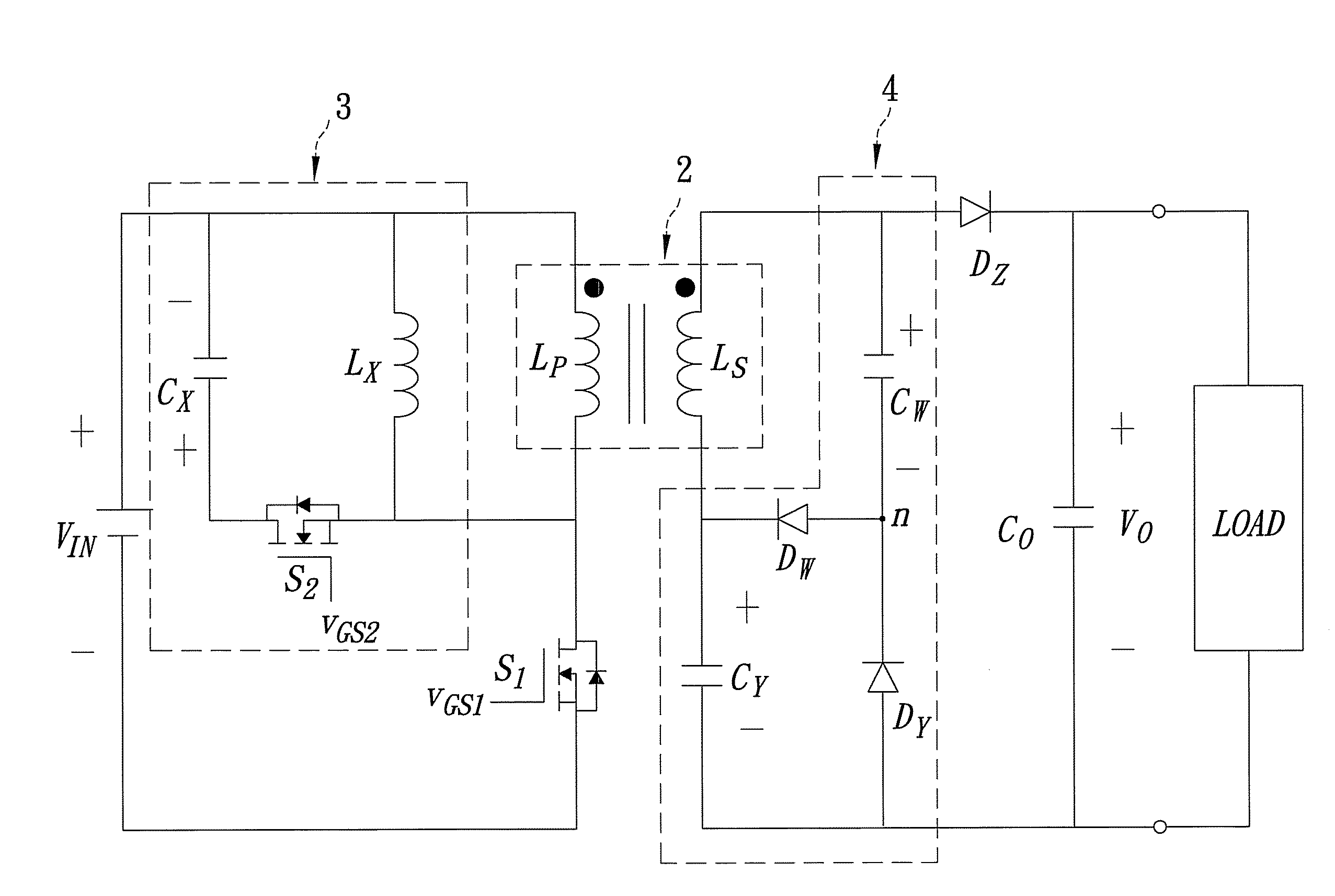
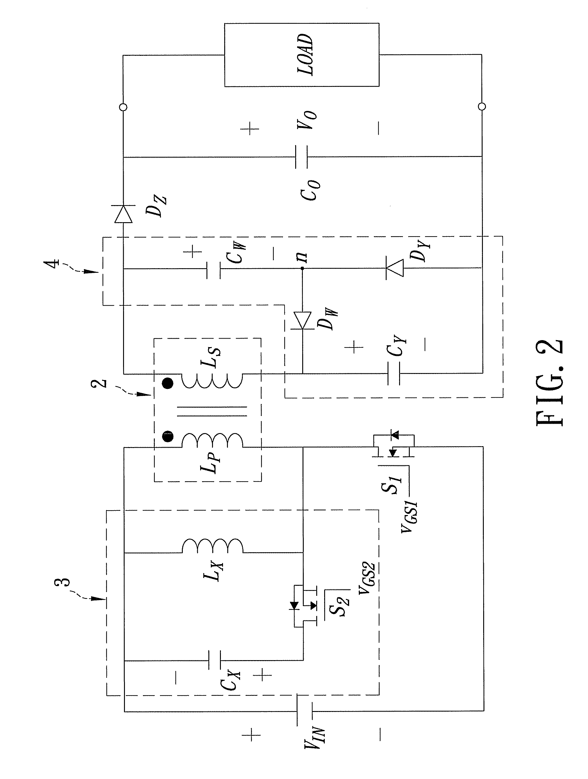
[0043]Referring to FIG. 2, the preferred embodiment of a boost device according to the present invention is shown to be adapted for boosting an input voltage (VIN) supplied by an external source to an output voltage (VO). The boost device includes a transformer 2, a first switch (S1), a clamp circuit 3, an output diode (DZ), a boost circuit 4, and an output capacitor (CO).

[0044]The transformer 2 includes first and second windings (LP, LS) wound around an iron core (not shown). A winding ratio of the first and second windings (LP, LS) is equal to 1:N. Each of the first and second windings (LP, LS) has a polarity end serving as a first end, and a non-polarity end serving as a second end. The polarity end of the first winding (LP) is adapted to be coupled to the external power source for receiving the input voltage (VIN).

[0045]The first switch (S1) is coupled between a reference node, such as ground, and the non-polarity end of the first winding (LP). The first switch (S1) has a contro...


PUM


Abstract

A boost device boosts an input voltage to an output voltage across an output capacitor, and includes an output diode coupled to the output capacitor, and a transformer coupled to a first switch, a clamp circuit and a boost circuit. The clamp circuit is coupled across a first winding of the transformer, and includes a clamp capacitor coupled in series to a second switch. The output capacitor is capable of being charged through the output diode with an induced voltage across a second winding of the transformer. The boost circuit is capable of being charged with the induced voltage across the second winding, and of charging the output capacitor so as to boost the output voltage across the output capacitor.

Description

BACKGROUND OF THE INVENTION[0001]1. Field of the Invention[0002]The invention relates to a boost device, more particularly to a DC-to-DC boost device.[0003]2. Description of the Related Art[0004]FIG. 1 illustrates a conventional boost device disclosed in U.S. Pat. No. 7,161,331. The conventional boost device includes a coupling circuit 10, a switch 13, a first diode 121, a second diode 122, an output diode 123, a first capacitor 141, a second capacitor 142, and an output capacitor 143. The coupling circuit 10 includes a first winding 11 and a second winding 12 each having a polarity end and a non-polarity end. The polarity end of the first winding 11 is coupled to an external power source. The first diode 121 has an anode coupled to the non-polarity end of the first winding 11, and a cathode coupled to an anode of the second diode 122. A cathode of the second diode 122 is coupled to the non-polarity end of the second winding 12 and an anode of the output diode 123. The first capacit...

Claims


Application Information

Patent Timeline
IPC IPC(8): H02M3/335
CPCH02M3/33569H02M3/01
Inventor DUAN, ROU-YONGLUO, RONG-DA
Owner HUNGKUANG UNIV
Why Eureka
Try Eureka