
Vehicle propulsion system with multi-channel DC bus and method of manufacturing same

a technology of dc bus and propulsion system, which is applied in the direction of propulsion by capacitors, dynamo-electric converter control, battery/fuel cell control arrangement, etc., can solve the problems of increasing the overall size, weight and cost of the system, reducing the operating efficiency and fuel economy of the individual components of the propulsion system, and reducing the overall system efficiency

Active Publication Date: 2015-07-30
GENERAL ELECTRIC CO
View PDF7 Cites 22 Cited by
  • Summary
  • Abstract
  • Description
  • Claims
  • Application Information

AI Technical Summary

Benefits of technology

This patent describes an apparatus and system for a vehicle propulsion system that includes a bi-directional DC-to-DC and a DC-to-AC voltage inverter, along with an energy storage system and a multi-channel DC bus assembly. The system has the capability to boost the voltage of its energy storage system to a different level than the DC bus voltage, allowing for more efficient use of the energy storage system. The technical effects of this system may include improved performance and efficiency of the vehicle propulsion system.

Problems solved by technology

While propulsion system configurations for purely electric vehicles and hybrid electric vehicles have been developed to include multiple sources of electrical energy to increase energy or power density and multiple power sources to achieve desired propulsive output, incorporating these energy storage and power sources into a propulsion system increases the overall size, weight, and cost of the system.
Further, the limitations imposed by configuring a propulsion system to operate with multiple power sources in combination with one or more energy storage sources reduces the operating efficiency and fuel economy of the individual components of the propulsion system in addition to reducing the overall system efficiency.

Method used


Image

  • Vehicle propulsion system with multi-channel DC bus and method of manufacturing same
  • Vehicle propulsion system with multi-channel DC bus and method of manufacturing same
  • Vehicle propulsion system with multi-channel DC bus and method of manufacturing same

Examples


Embodiment Construction

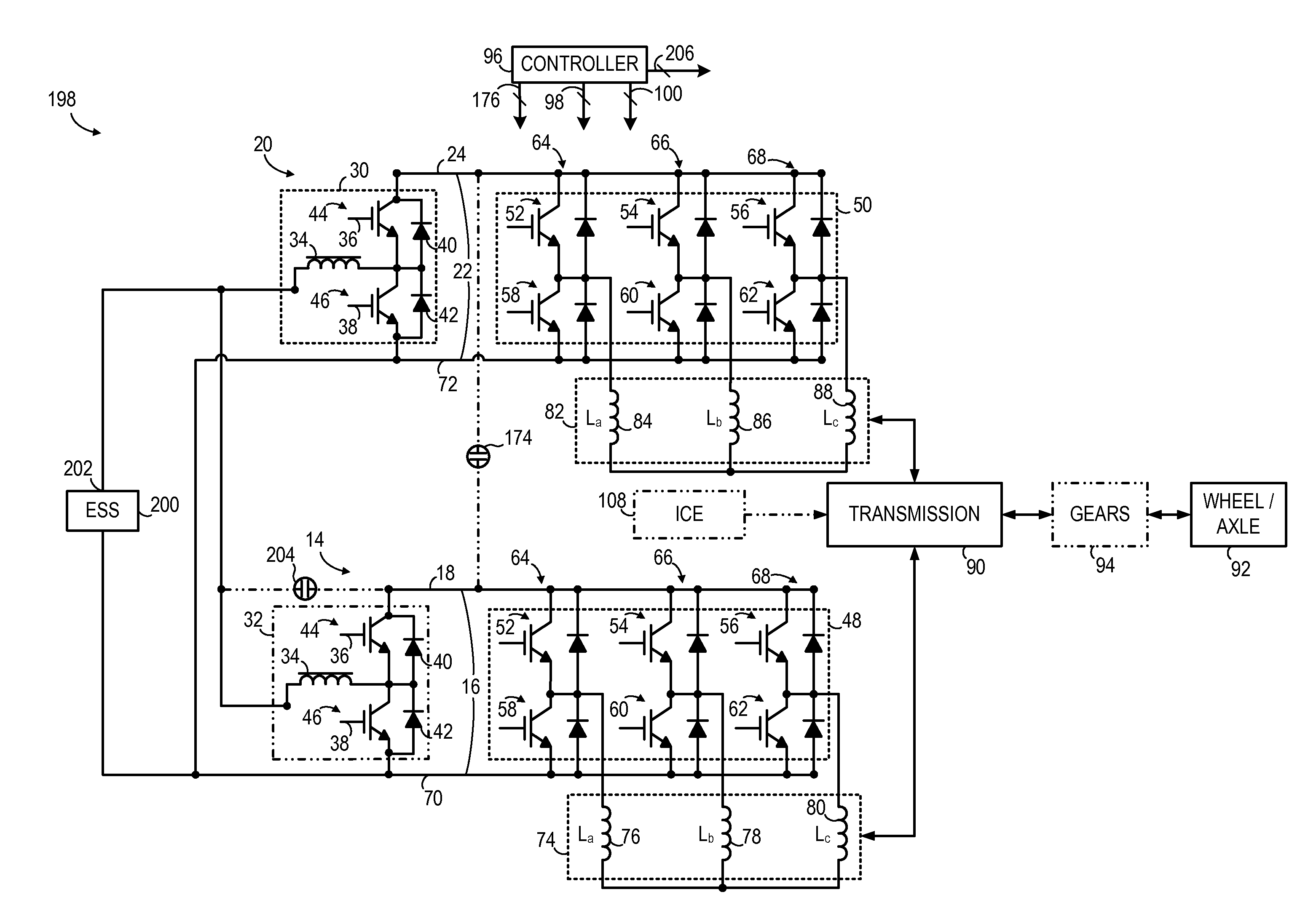
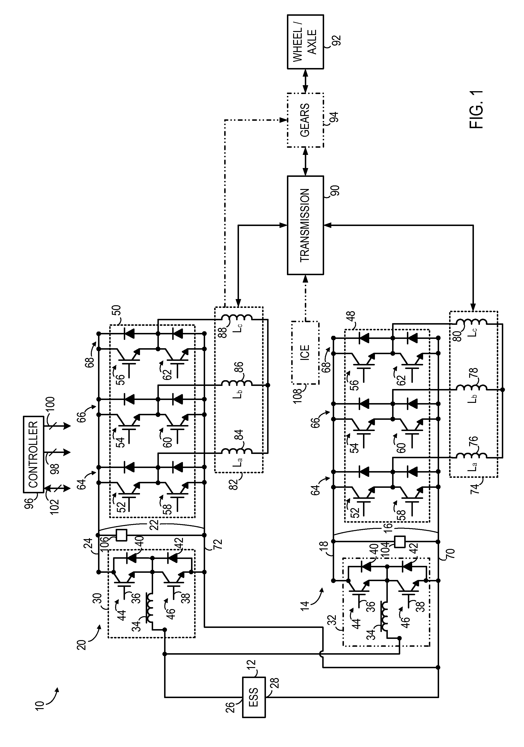
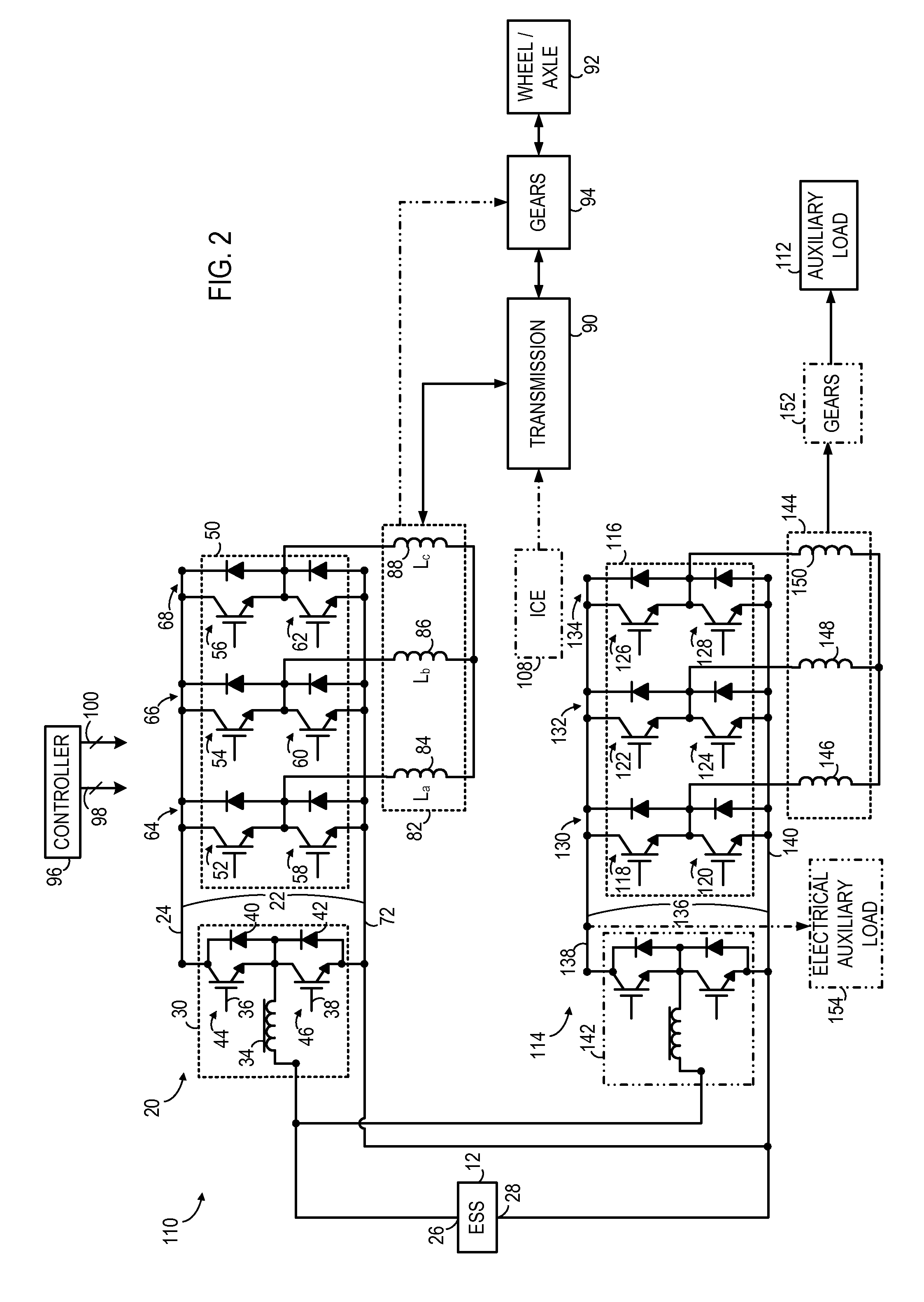
[0020]FIG. 1 is a schematic diagram of a propulsion system 10 according to an embodiment of the invention. As described in detail below, propulsion system 10 may be configured in a pure electric (EV) propulsion system arrangement that splits power output between two or more electromechanical devices or as a hybrid (HEV) propulsion system that includes an internal combustion engine in addition to multiple electromechanical devices. In either an EV or HEV embodiment, the electromechanical devices are provided on independent channels of a multi-channel DC bus, permitting flexibility in the sizing and operation of the multiple electromechanical devices and increasing the operating efficiency of the electromechanical devices and overall propulsion system.

[0021]According to various embodiments, propulsion system 10 is configured to be incorporated into various types of vehicles including, but not limited to, automobiles, busses, trucks, tractors, mining equipment, marine craft, and off-ro...


PUM

PropertyMeasurementUnit
DC link voltageaaaaaaaaaa

Abstract

An apparatus includes a multi-channel DC bus assembly comprising a first channel and a second channel, a first electromechanical device coupled to a positive DC link of the first channel, and a second electromechanical device coupled to a positive DC link of the second channel. A first DC-to-AC voltage inverter is coupled to the positive DC link of the first channel and a second DC-to-AC voltage inverter is coupled to the positive DC link of the second channel. The apparatus further includes a bi-directional voltage modification assembly coupled to the positive DC link of the second channel and a first energy storage system electrically coupled to the first electromechanical device.

Description

BACKGROUND OF THE INVENTION[0001]Embodiments of the invention relate generally to electric drive systems including hybrid and electric vehicles and, more particularly, to transferring energy between one or more energy storage devices and multiple electromechanical devices of the vehicle using a multi-channel DC bus.[0002]Purely electric vehicles use stored electrical energy to power an electric motor, which propels the vehicle and may also operate auxiliary drives. Purely electric vehicles may use one or more sources of stored electrical energy. For example, a first source of stored electrical energy may be used to provide longer-lasting energy while a second source of stored electrical energy may be used to provide higher-power energy for, for example, acceleration.[0003]Hybrid electric vehicles may combine an internal combustion engine and an electric motor powered by an energy storage device, such as a traction battery, to propel the vehicle. Such a combination may increase overa...

Claims


Application Information

Patent Timeline
Patent Type & Authority Applications(United States)
IPC IPC(8): B60L11/18H05K13/00B60L50/16
CPCH05K13/0023B60L11/1803B60L50/50H05K13/00B60L7/14B60L15/007B60L2210/12B60L2210/14B60L2210/40B60L15/2045B60L50/40B60L50/16B60L50/51B60L58/18B60L58/21B60L58/20Y10T29/49117Y02T10/64Y02T90/40Y02T90/14Y02T10/62B60L53/24H02M3/00H02M7/42B60Y2200/91B60Y2200/92Y02T10/7072Y02T10/72Y02T10/70B60L50/10
Inventor KING, ROBERT DEANLI, ZHIHAO
Owner GENERAL ELECTRIC CO
Learn More