Seal Structure and Control Method Therefor

a technology of sealing structure and sealing layer, which is applied in the direction of machines/engines, mechanical equipment, liquid fuel engines, etc., can solve the problems of frictional heat generated heat accumulated in the thermal insulation layer is transmitted to the rotating portion, and the rotor does not rotate smoothly, so as to improve the sealing performance, smooth start up the steam turbine, and suppress the effect of rotating portion temperature ris

Inactive Publication Date: 2010-11-04
MITSUBISHI HITACHIPOWER SYST LTD
View PDF25 Cites 13 Cited by
  • Summary
  • Abstract
  • Description
  • Claims
  • Application Information

AI Technical Summary

Benefits of technology

[0018]The aspect of the present invention can provide the seal structure and the control method therefor that can improve sealing performance between the rotating portion and the fixe

Problems solved by technology

In the technology disclosed in JP-2007-16704-A, however, if the rotating portion is continuously rotated for a long period of time so that the fins and the abradable metal are in contact with each other for a long period of time, the frictional heat thus generated is accumulated in the thermal insulation layer.
This poses a problem in that the heat accumulated in the thermal insulati

Method used


Image

  • Seal Structure and Control Method Therefor
  • Seal Structure and Control Method Therefor
  • Seal Structure and Control Method Therefor

Examples


Embodiment Construction

[0032]Embodiments of the present invention will hereinafter be described in detail with reference to the drawings.

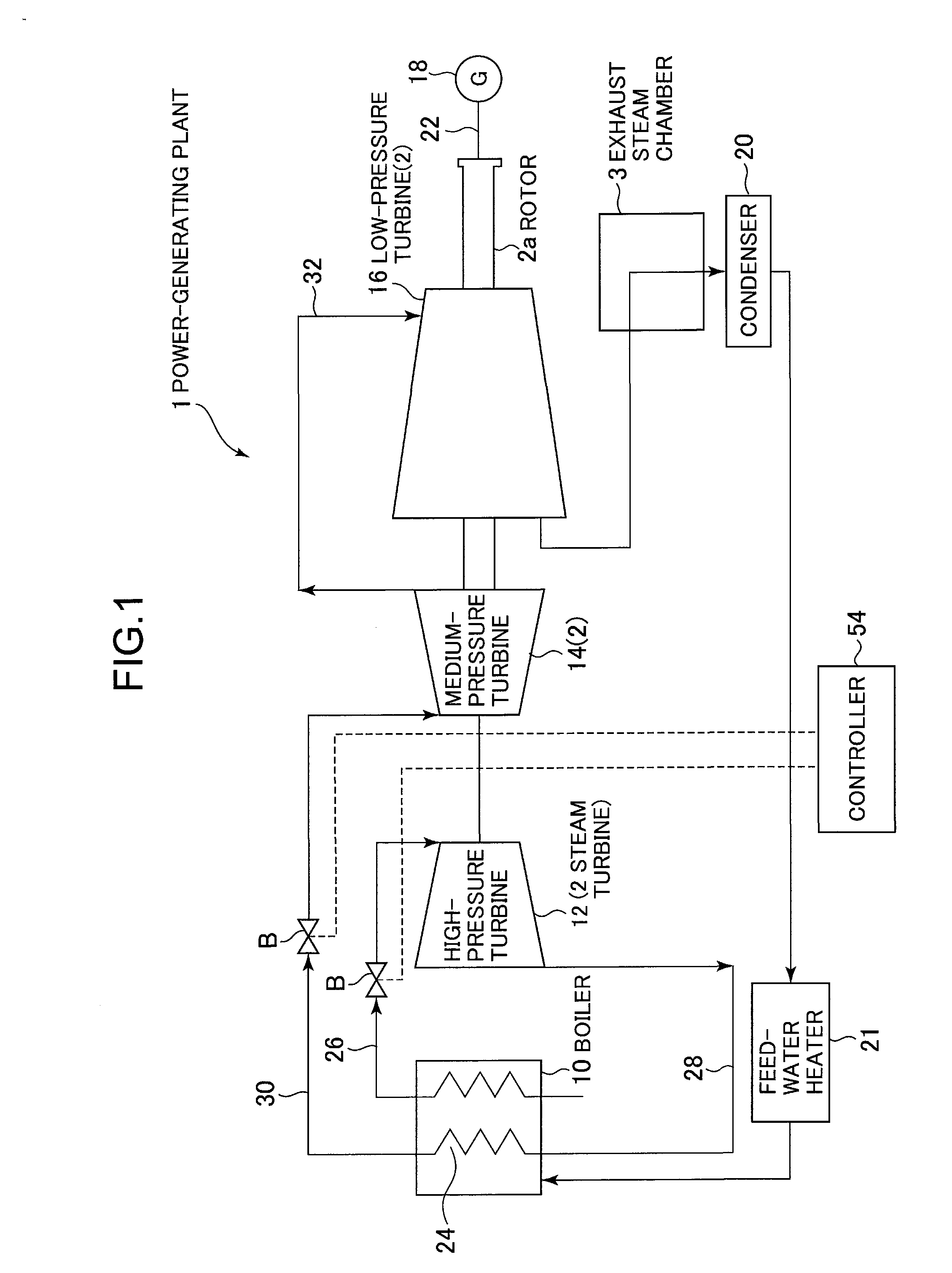
[0033]Referring to FIG. 1, a power-generating plant 1 is configured to include a boiler 10, a steam turbine 2 (a high-pressure turbine 12, a medium-pressure turbine 14, and a low-pressure turbine 16), a generator 18, and a condenser 20. A rotor 2a of the low-pressure turbine 16 is coupled to a drive shaft 22 of the generator 18. Rotation of the low-pressure turbine 16 drives the generator 18 for electric generation.

[0034]The boiler 10 is a steam generator, which is provided with a reheater 24. The boiler 10 is connected to an inlet side of the high-pressure turbine 12 via a pipe 26. An outlet side of the high-pressure turbine 12 is connected to the reheater 24 of the boiler 10 via a pipe 28. The reheater 24 is connected to an inlet side of the medium-pressure turbine 14 via a pipe 30. An outlet side of the medium-pressure turbine 14 is connected to an inlet side of the l...


PUM


Abstract

Provided are a seal structure and a control method therefor that can improve sealing performance between a rotating portion and a fixed portion, smoothly start up a steam turbine, and suppress the temperature rise of the rotating portion even if the rotating portion is continuously rotated for a long period of time.
A seal structure is configured such that seal fins 62 on a seal base-plate 61 side and corresponding breathable spacers 4b on a rotor 2a side are opposed to each other and breathable spacers 4a on the seal base-plate 61 side and corresponding seal fins 2a1 on the rotor 2a side are opposed to each other. The seal base-plate 61 is installed shiftably in a direction coming close to or moving away from the rotor 2a. If steam St has low pressure, the seal fins 62 and the corresponding breathable spacers 4b are not in contact with each other and the seal fins 2a1 and the corresponding breathable spacers 4a are not in contact with each other. If the steam St has high pressure, the seal fins 62 and the corresponding breathable spacers 4b are in contact with each other and the seal fins 2a1 and the corresponding breathable spacers 4a are in contact with each other.

Description

BACKGROUND OF THE INVENTION[0001]1. Field of the Invention[0002]The present invention relates to a seal structure provided for a steam turbine and a control method therefor.[0003]2. Description of the Related Art[0004]For power-generating plants in which a turbine (steam turbine) is rotated for electric generation by steam generated by a steam generator such as a boiler or the like, the steam turbine includes a high-pressure turbine, a medium-pressure turbine and a low-pressure turbine installed in that order from the upstream side of steam flow. The steam having rotated the low-pressure turbine is introduced via an exhaust hood into a condenser, in which the steam is condensed as feed-water, which is returned to the steam generator.[0005]In the steam turbine constituting part of the power-generating plant as described above, a stator blade secured to the inside of a casing is disposed between rotor blades rotated integrally with a rotor. In this way, the stator blade and the rotor ...

Claims


Application Information

Patent Timeline
IPC IPC(8): F04D29/10
CPCF01D1/02F05D2240/55F01D11/08F01D11/14
Inventor NARITA, KENJIROYAMAZAKI, HARUYUKIDOI, HIROYUKIKOBAYASHI, KEITORIYA, HAJIMEKUDO, TAKESHIKOJIMA, YOSHITAKA
Owner MITSUBISHI HITACHIPOWER SYST LTD
Why Eureka
Try Eureka