Planetary gear set and power transmitting apparatus and use of the same

a transmission device and gear set technology, applied in the direction of belts/chains/gearings, toothed gearings, belts/chains/gearings, etc., can solve the problems of low fuel efficiency of automatic transmission, low transmission efficiency, easy manipulation of automatic transmission, etc., to reduce the loss of torque of the transmission process of planetary gear sets, the effect of weak torqu

Inactive Publication Date: 2010-11-04
HA TAE HWAN
View PDF15 Cites 6 Cited by
  • Summary
  • Abstract
  • Description
  • Claims
  • Application Information

AI Technical Summary

Benefits of technology

[0010]And yet another object of the present invention is to provide a power transmission apparatus in which the loss of torque of the transmit process of the planetary gear set can be minimized, so that it is able to operate between various transmit steps using a transmit power source which supplies relatively weak torque.
[0011]Finally yet another object of the present invention is to provide a power transmission apparatus in which, the slip that may be occurred at connect portions between operative members of the planetary gear set and the transmit power source, may be minimized.

Problems solved by technology

The manual transmission has high fuel efficiency but difficult to manipulate, while the automatic transmission is easy to manipulate but has low fuel efficiency.
Therefore, for the automatic transmission, the greater the number of transmit steps, the greater the number of the planetary gear sets and the friction elements becomes, which results in weight increase of the automatic transmission, hence lowering the fuel efficiency.
However, between the drive power source and the input shaft a damper clutch is mounted, so the additional devices could not be connected to the input shaft.
Therefore space for mounting the additional devices is insufficient.
According to the above methods, however, the torque of the drive power source was to be applied to the transmit power source, which causes serious loss of the torque.

Method used


Image

  • Planetary gear set and power transmitting apparatus and use of the same
  • Planetary gear set and power transmitting apparatus and use of the same
  • Planetary gear set and power transmitting apparatus and use of the same

Examples


first embodiment

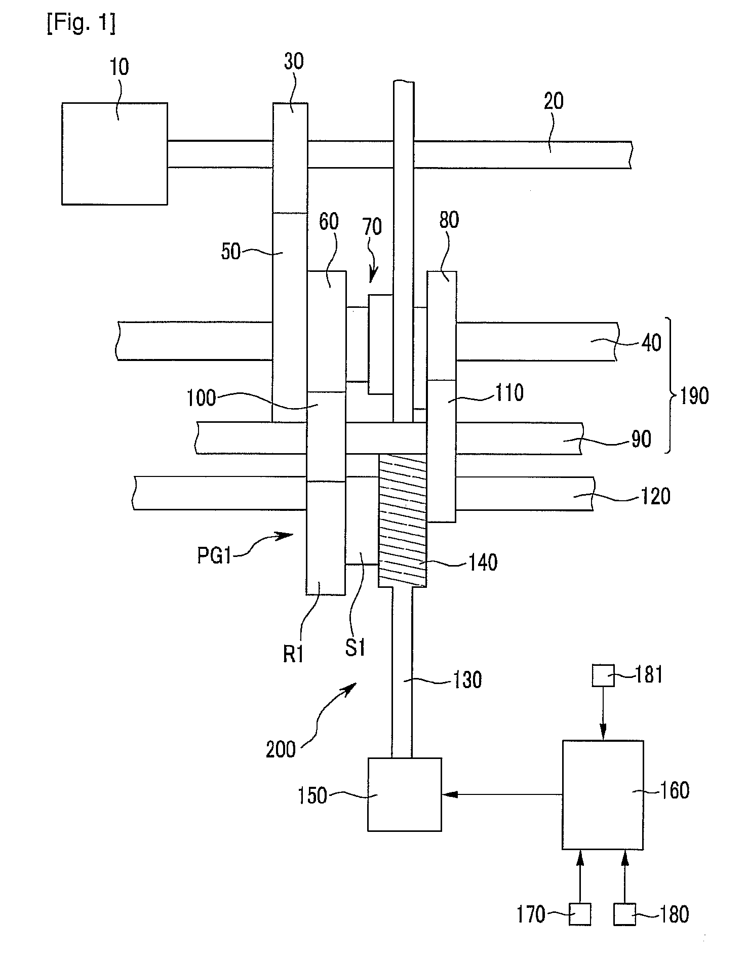
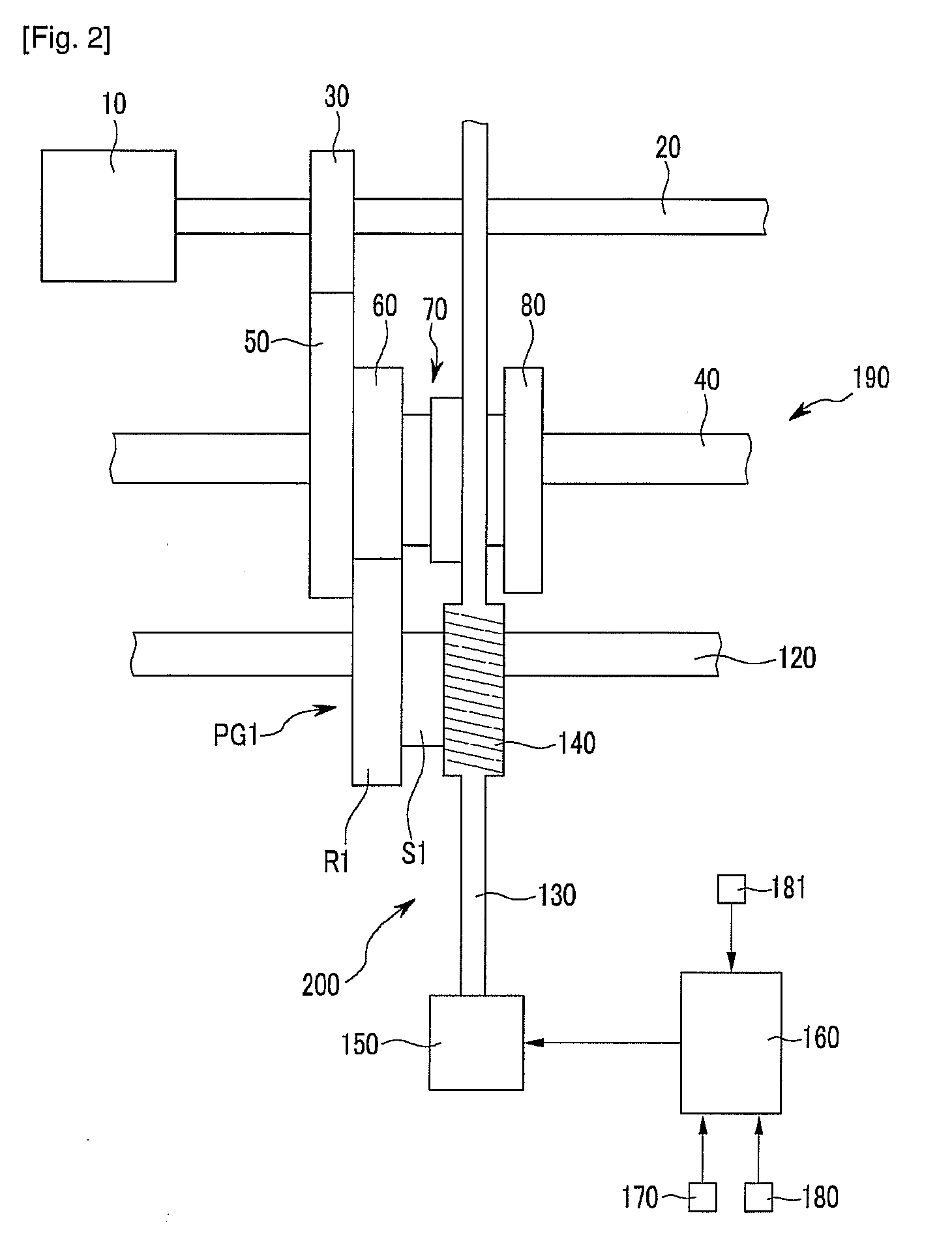
[0051]FIG. 1 is a schematic representative view illustrating construct of a power transmitting apparatus of the invention, FIG. 2 is a schematic representative view illustrating construct of the power transmitting apparatus of FIG. 1 omitted an idle shaft, and FIG. 3 is a schematic representative view illustrating construct of the power transmitting apparatus of FIG. 2 omitted an transmit input shaft.

[0052]As shown in FIGS. 1 to 3, a power transmitting apparatus according to first embodiment of the invention includes an input shaft 20, a reduction unit 190, a planetary gear set PG1, an output shaft 120, a transmit unit 200, and a control part 160.

[0053]The input shaft 20 has its one end connected directly to a drive power source 10 for being supplied with the rotate speed of the drive power source 10. A drive gear 30 is fixed on the input shaft 20 such that the input shaft 20 and the drive gear 30 rotate at same speed together. The drive power source 10 may be a gasoline, a diesel,...

second embodiment

[0082]As shown in FIGS. 5 and 6, the power transmitting apparatus of the invention includes an input shaft 20, a reduction unit 190, a planetary gear set PG1, an output shaft 120, a transmit unit 200, and a control part (160: refer to FIGS. 1 and 2).

[0083]Detailed description concerning the input shaft 20, the planetary gear set PG1, the output shaft 120, and the control part (160) will be omitted.

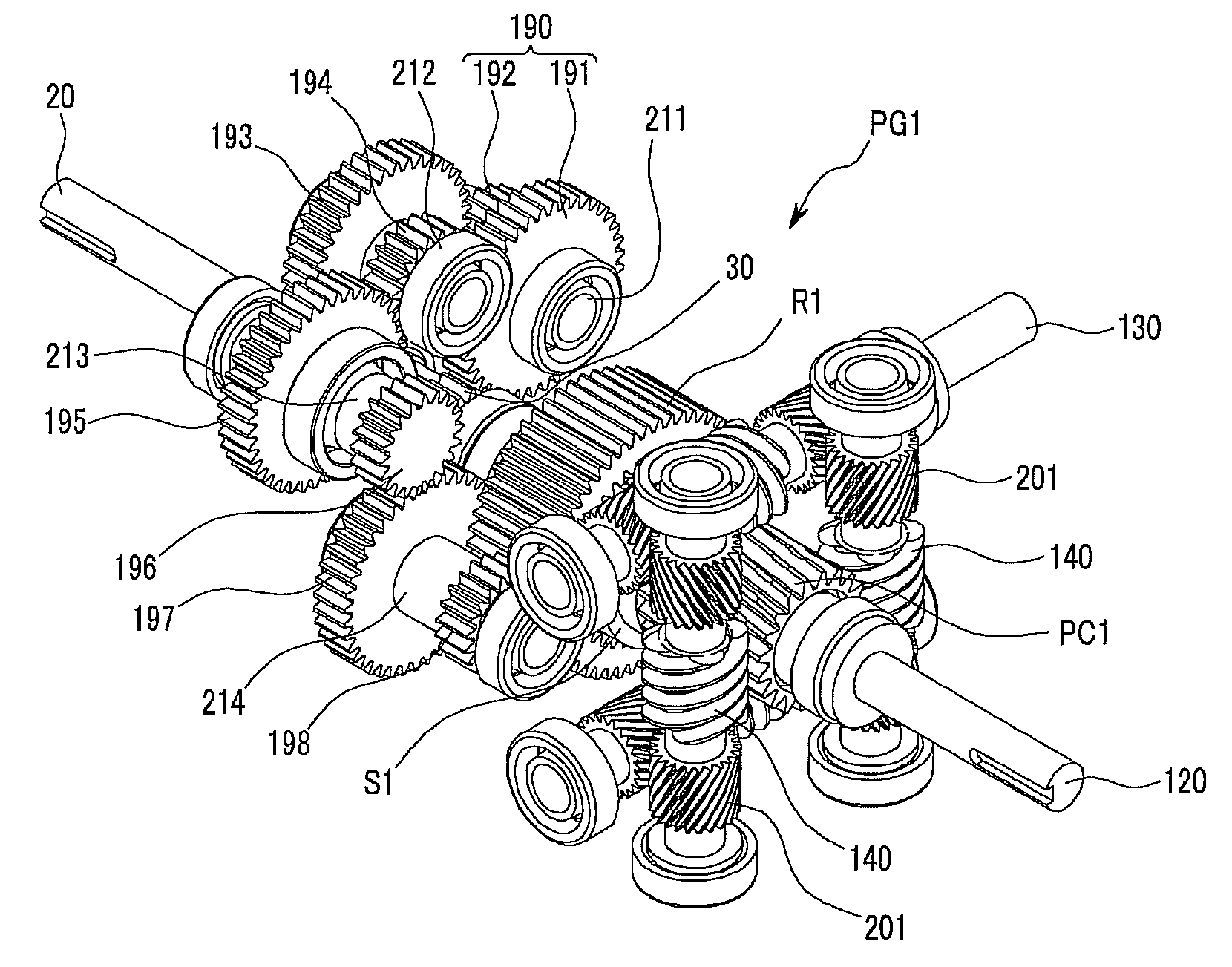
[0084]In the power transmitting apparatus according to second embodiment of the invention, the reduction unit 190 includes four shafts 211, 212, 213, and 214 which are aligned parallel to the input shaft 20, and eight gears 191, 192, 193, 194, 195, 196, 197, and 198, every two of which are respectively mounted on each of the shafts 211, 212, 213, and 214.

[0085]On a first shaft 211, first and second gears 191 and 192 having different numbers of gear teeth are mounted, and the first gear 191 is gear-connected to the drive gear 30 of the input shaft 20. The number of gear teeth of the first ...


PUM


Abstract

The present invention relates to a planetary gear set and a power transmitting apparatus. In the planetary gear set, a gear tooth is formed by extending one side of a planetary carrier. In the power transmitting apparatus, multi-stage transmission is enabled by reducing a rotational speed inputted from a power-driving source and then inputting the reduced rotational speed to one operational member of the planetary gear set as well as the rotational speed of a speed changing power source to another operational member of the planetary gear set. According to an embodiment of the present invention, the power transmitting apparatus comprises: an input shaft to which a driving gear is fixed and of which one end is constantly connected to the power driving source; a decelerating unit which is combined with the driving gear and decreases the rotational speed of the input shaft; a planetary gear set including a first operational member which receives the rotational speed from the input shaft by being connected to the decelerating unit, a second operational member which receives the power for speed changing, and a third operational member at which an output speed is generated; a speed changing unit which receives the power for speed changing by being constantly connected to the speed changing power source and that is also connected to the second operational member in order to transmit the power for speed changing to the second operational member; and an output shaft which is fixed to the third operational member of the planetary gear set to transmit the output speed, wherein the operational shaft of the second operational member may be perpendicular to the rotational shaft of the speed changing unit.

Description

FIELD OF THE INVENTION[0001]The invention relates generally to a planetary gear set and power transmitting apparatus using the same which may be employed in automobiles, vessels, windmills, and converter motors et cetera, more particularly to a power transmitting apparatus that comprises a planetary gear set having planet carrier extended from one side and formed gear teeth at the extended portion, wherein the rotate speed from a drive power source is reduced to be inputted to an operative member of the planetary gear set and the rotate speed from a transmit power source is inputted to another operative member of the planetary gear set so that multiple transmit steps may be realized.BACKGROUND ART[0002]As is generally known, a transmission is an apparatus that transmits the input power from a drive power source to an output shaft, after altering the input power to a suitable rotate speed according to driving conditions. The transmissions include the manual transmission that a driver...

Claims


Application Information

Patent Timeline
Patent Type & Authority Applications(United States)
IPC IPC(8): F16H3/44
CPCF16H3/72F16H3/44
Inventor HA, TAE-HWAN
Owner HA TAE HWAN
Why Eureka
Try Eureka