Hybrid drive of a motor vehicle

a hybrid drive and motor vehicle technology, applied in mechanical equipment, transportation and packaging, gearing, etc., can solve the problems of low transmission efficiency in electric driving mode, large number of shift elements to be engaged and disengaged, and high total number of required shift elements, so as to save installation space and manufacturing costs, the effect of high transmission efficiency

Inactive Publication Date: 2017-09-19
ZF FRIEDRICHSHAFEN AG
View PDF28 Cites 5 Cited by
  • Summary
  • Abstract
  • Description
  • Claims
  • Application Information

AI Technical Summary

Benefits of technology

The patent describes a phase shifter gearbox for vehicles with electric machines and a manual transmission. The technical effects of the patent include a more efficient and range-oriented electric driving mode through a reduction stage between the electric machine and the phase shifter gearbox, with higher torque and weaker rotation speed. The fixed gears of the manual transmission are arranged in a torque-proof manner to avoid rolling and drag losses. The gear of the manual transmission can be connected to the output shaft in a torque-proof manner through a gear shift element and a coupling shift element, which saves installation space and manufacturing costs. The shift elements are preferably formed as unsynchronized claw clutches, which are cost-effective, compact, and easy to control. The design of the relevant shift elements allows for a compact and efficient shifting technology that saves space.

Problems solved by technology

The small number of gear steps available in the internal combustion engine driving mode and, based on the drag losses of the spur gear stages, the low transmission efficiency in the electric driving mode can be specified as disadvantages of such hybrid drive.
However, disadvantages with such hybrid drive include the high total number of required shift elements, the large number of shift elements to be engaged and disengaged for most gears, and the poor transmission efficiency in the winding-path gears.

Method used


Image

  • Hybrid drive of a motor vehicle
  • Hybrid drive of a motor vehicle
  • Hybrid drive of a motor vehicle

Examples


first embodiment

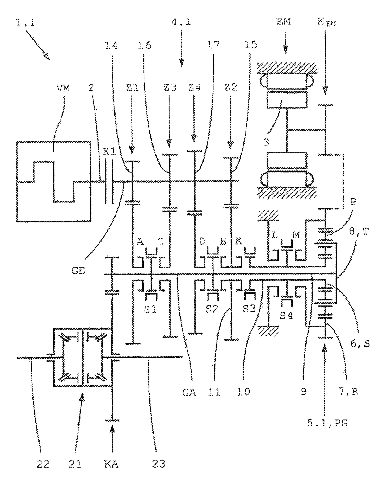
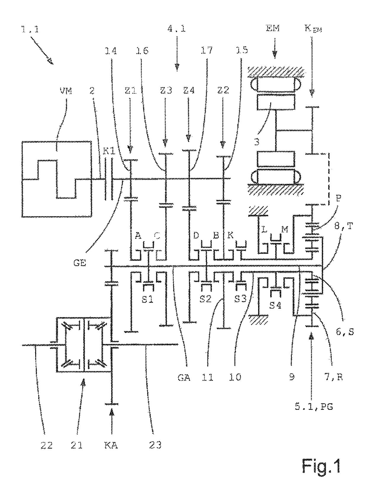
[0056]the hybrid drive 1.1, schematically shown in FIG. 1, formed in accordance with the characteristics of the invention features an internal combustion engine VM with a drive shaft 2, an electric machine EM operable as a motor and as a generator with a rotor 3, an automated manual transmission 4.1 formed in a lay-shaft design with one input shaft GE and one output shaft GA, along with a phase shifter gearbox 5.1 carried out in a planetary design with two input elements 6, 7 and one output element 8.

[0057]The input shaft GE of the manual transmission 4.1 is connected on the input side to the drive shaft 2 of the internal combustion engine VM through a separating clutch K1 formed as a friction clutch. Within the transmission, the input shaft GE of the manual transmission 4.1 can be brought into drive connection with the output shaft GA through four selectively shiftable spur gear stages Z1, Z2, Z3, Z4, each consisting of a fixed gear 14, 15, 16, 17 and one idler gear. The fixed gear...

fifth embodiment

[0077]a hybrid drive 1.5 formed in accordance with the characteristics of the invention schematically shown in FIG. 5 differs, with a similar functioning, from the hybrid drive 1.2 according to FIG. 2 by a manual transmission 4.5 with five gears G1, G2, G3, G4, G5 and a bypass shift element M′ formed as a friction clutch.

[0078]The input shaft GE of this manual transmission 4.5 can now be brought into drive connection with the output shaft GA through five selectively shiftable spur gear stages Z1, Z2, Z3, Z4, Z5, each consisting of one fixed gear and one idler gear. The five fixed gears 14, 15, 16, 17, 18 of the five spur gear stages Z1-Z5 are arranged in a torque-proof manner at the input shaft GE. The four idler gears of the first, second, fourth and fifth spur gear stages Z1, Z2, Z4, Z5 are rotatably mounted on the output shaft GA, and are connectable in a torque-proof manner to the output shaft GA through associated gear shift elements A, B, D, E, which are combined in pairs into...

sixth embodiment

[0082]The sixth embodiment, schematically shown in FIG. 6, of a hybrid drive 1.6 formed in accordance with the characteristics of the invention is based on the hybrid drive 1.3 according to FIG. 3. In contrast to the latter, the spur gear stages Z1, Z2 of the first gear G1 and the second gear G2 of the manual transmission 4.6 are now arranged in different gear levels, and each accordingly features its own fixed gear 14, 15 secured in a torque-proof manner at the input shaft GE. As a result, there is a greater freedom in calculating the transmission ratios of the four gears G1-G4, which can be used, for example, for the realization of a progressive gear gradation of the manual transmission 4.6.

[0083]An additional difference with the hybrid drive 1.3 according to FIG. 3 consists of the fact that, in the present case, both the bypass shift element M′ and the locking shift element L′ are formed as friction clutches. Thereby, in electric driving mode, both traction shifts and thrust shif...


PUM


Abstract

A hybrid drive of a motor vehicle has an internal combustion engine, an electric machine, an automated manual transmission with an input shaft and an output shaft, and a phase shifter gearbox in a planetary design with two input elements and one output element. A first input element of the gearbox is connected to a hollow shaft arranged in a coaxial manner around the output shaft, which is connectable to an idler gear of an axially adjacent spur gear stage of the manual transmission, and, for bypassing the gearbox, is connectable to the second input element or the output element of the gearbox. The second input element of the gearbox is permanently in drive connection with a rotor of the electric machine, and the output element of the gearbox is connected in a torque-proof manner to the output shaft.

Description

FIELD OF THE INVENTION[0001]The invention relates to a hybrid drive of a motor vehicle, which features an internal combustion engine with a drive shaft, an electric machine with a rotor operable as a motor and as a generator, an automated manual transmission carried out in a lay-shaft design with one input shaft and at least one output shaft, along with a phase shifter gearbox carried out in a planetary design with two input elements and one output element. The input shaft of the manual transmission is connected to the drive shaft of the internal combustion engine through a separating clutch and can be brought into drive connection with the output shaft through several selectively shiftable spur gear stages. The drive shaft of the internal combustion engine and the rotor of the electric machine are connectable in terms of drive technology to the output shaft of the manual transmission through the phase shifter gearbox drive.BACKGROUND[0002]It is generally known that, with a hybrid d...

Claims


Application Information

Patent Timeline
IPC IPC(8): B60K6/48B60W20/40F16H3/72B60K6/40F16H3/091B60K6/387B60K6/547F16H3/093B60K6/365F16H3/089
CPCB60K6/365B60K6/387B60K6/40B60K6/48B60K6/547B60W20/40F16H3/093F16H3/0915F16H3/725Y10S903/914Y10S903/951B60K2006/4808B60Y2200/92F16H2003/0931F16H2200/0043Y10S903/911B60W10/02B60W10/06B60W10/08B60W2710/0644B60W2710/081Y02T10/62
Inventor KALTENBACH, JOHANNESROSKE, MICHAELGRIESMEIER, UWE
Owner ZF FRIEDRICHSHAFEN AG
Why Eureka
Try Eureka