
Adjustable spinal rehabilitation device

Inactive Publication Date: 2010-11-04
SY HEALTH REHAB LLC
View PDF3 Cites 27 Cited by
  • Summary
  • Abstract
  • Description
  • Claims
  • Application Information

AI Technical Summary

Benefits of technology

[0004]A primary objective of the present invention is to provides an adjustable spinal rehabilitation device characterized by integration of a bed frame and an inverted U-shaped frame to enhance efficacy of rehabilitation therapy performed on a rehabilitation patient's cervical spine, thoracic spine, and lumbar spine, and efficacy of pelvic rehabilitation performed on the rehabilitation patient.
[0005]Another objective of the present invention is to provide an adjustable spinal rehabilitation device characterized by streamlined elevation adjustment mechanisms provided between the bed frame and pads such that it is easy to adjust inclination of both sides of the pads.
[0006]Yet another objective of the present invention is to provide an adjustable spinal rehabilitation device with three pads disposed on the bed frame, allowing inclination of both sides of each of the pads to be freely adjusted so as to render the rehabilitation bed fit for the rehabilitation patient lying thereon with a specific lying posture and therefore ensure the rehabilitation patient's comfort.
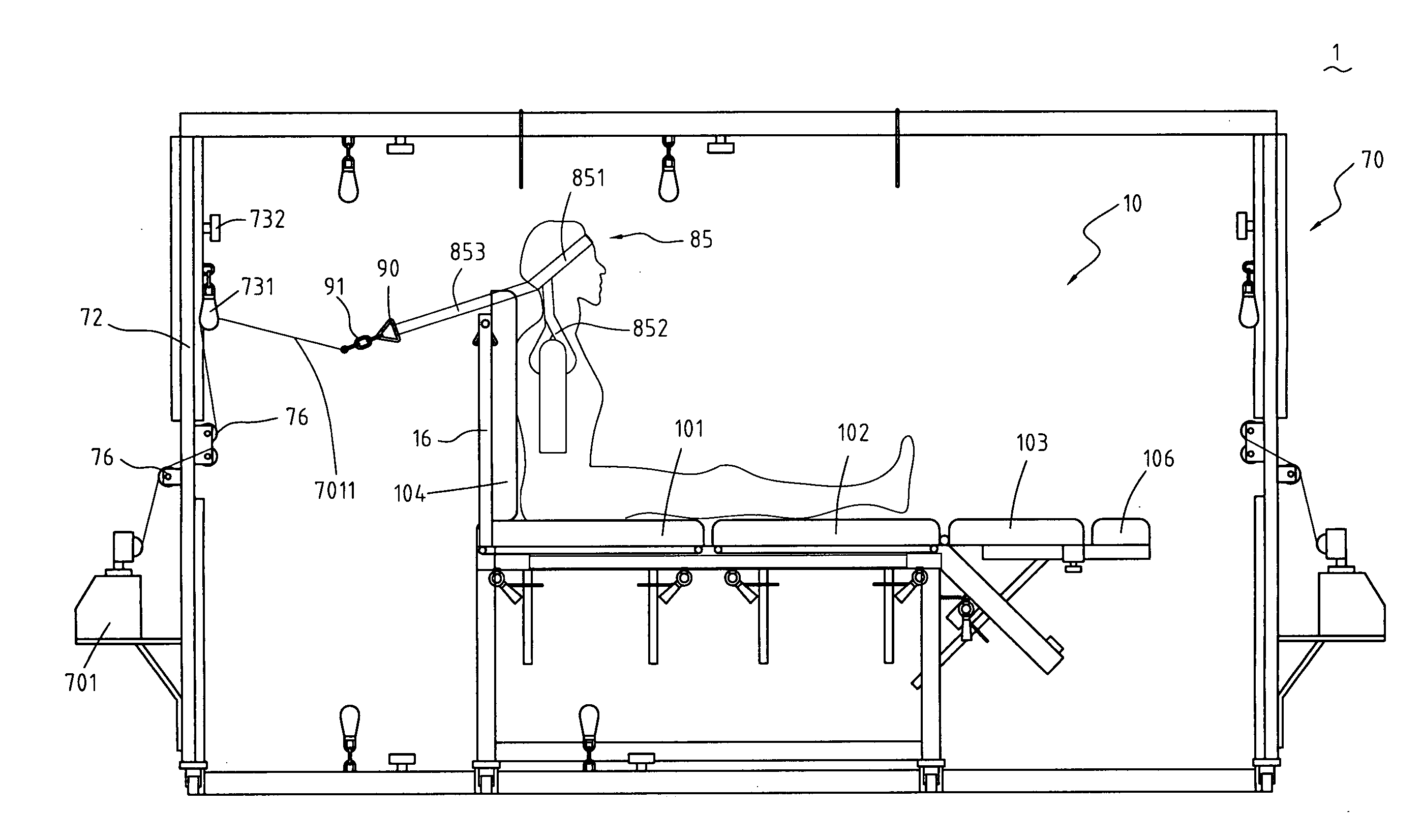
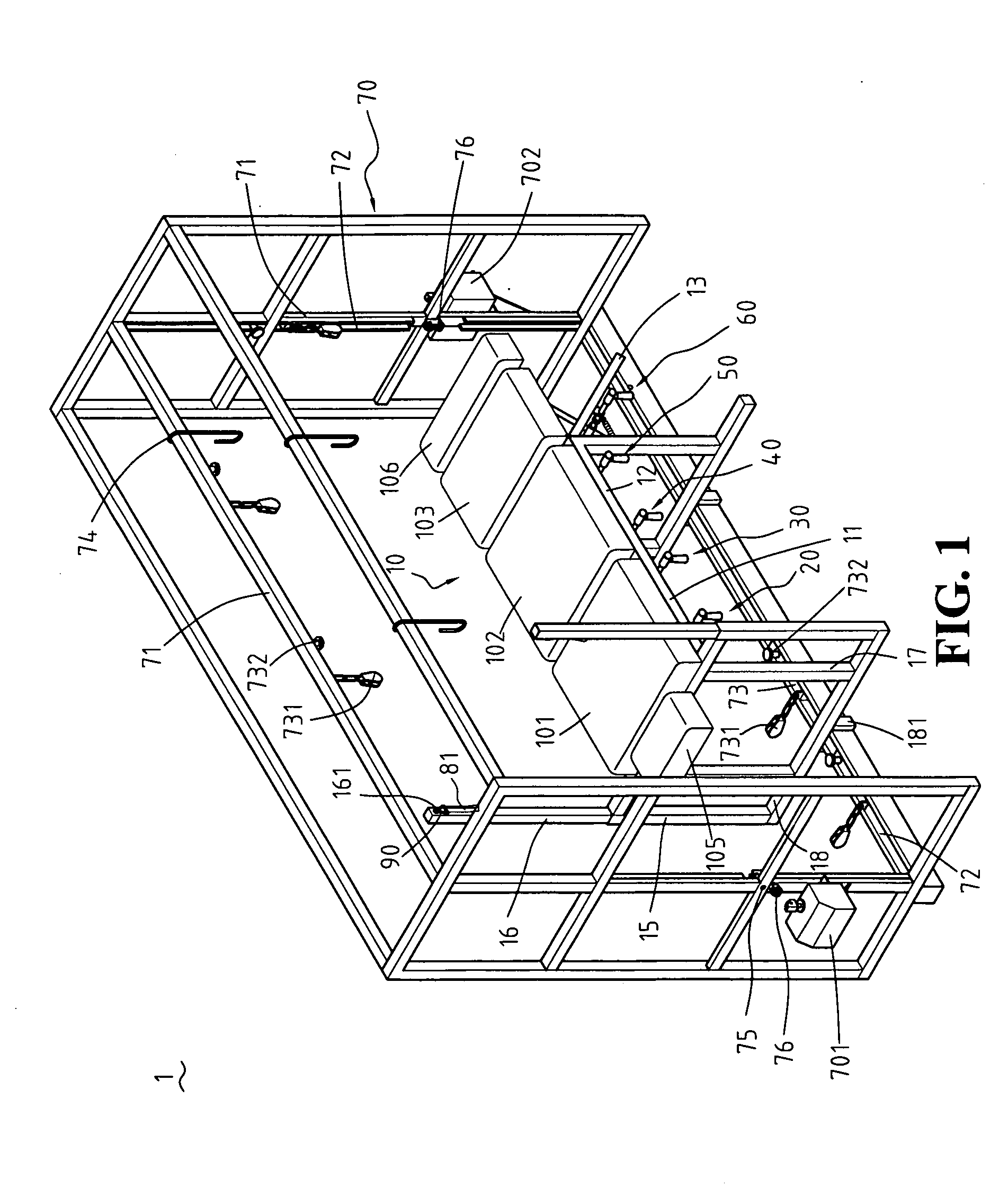
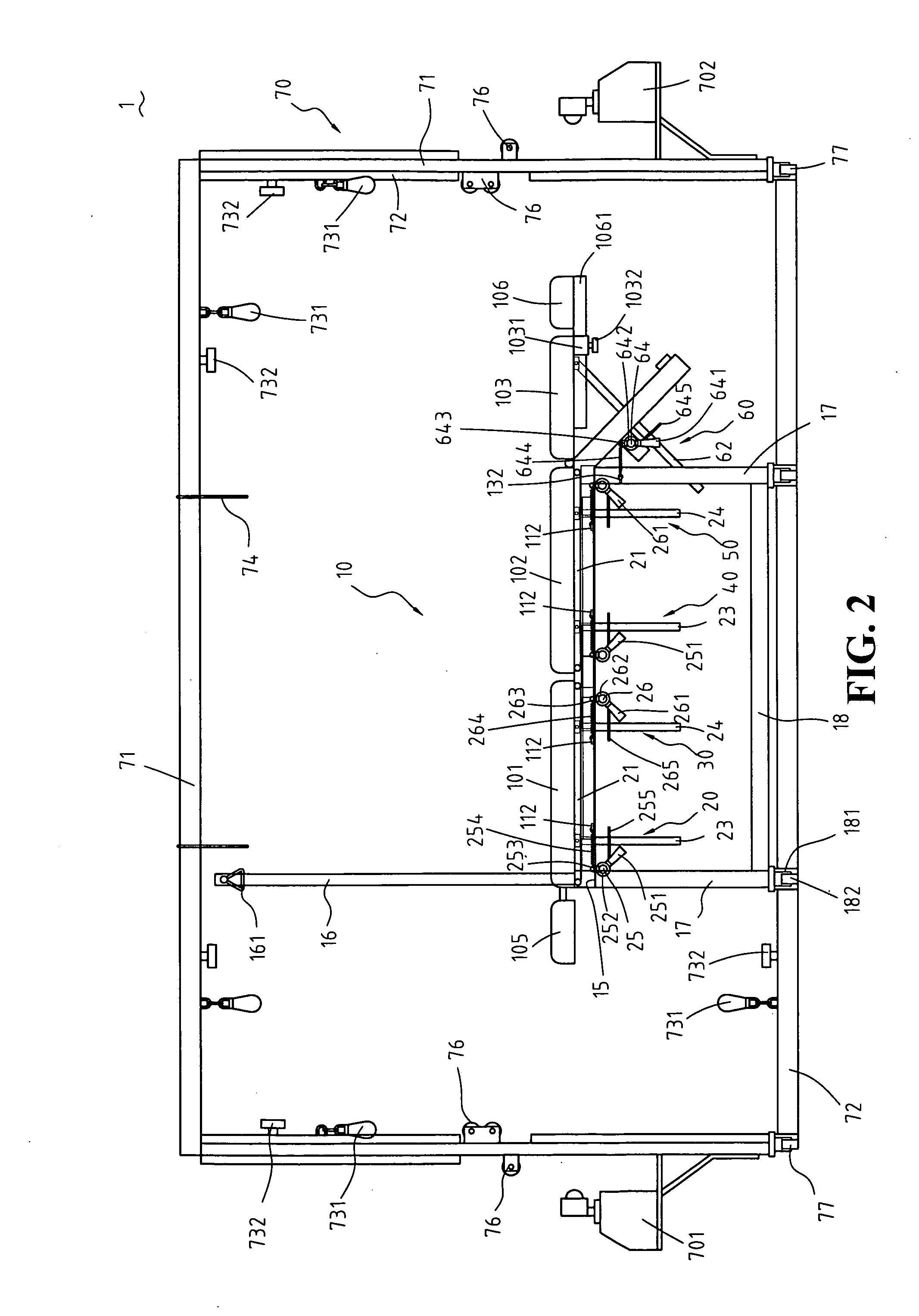
[0007]To achieve the above and other objectives, the present invention provides an adjustable spinal rehabilitation device, comprising: a bed frame, three soft pads, five elevation adjustment mechanisms, an inverted U-shaped frame, two tractors, and five fastening belts. The bed frame is provided with the three soft pads on which a rehabilitation patient lies. Four fastening belts are tied to the bed frame bilaterally such that the rehabilitation patient is fixed in position to the bed frame. The five elevation adjustment mechanisms are positioned between and coupled to the bed frame and the soft pads. Inclinations of the soft pads are adjustable with the five elevation adjustment mechanisms such that the rehabilitation patient lies on the soft pads comfortably. The inverted U-shaped frame is provided outside the bed frame. The bed frame is coupled to the inverted U-shaped frame from below. Two tractors are provided outside the inverted U-shaped frame. A cord is connected to and extended from each of the two tractors. The cords penetrate holes of the inverted U-shaped frame so as for the cords to be coupled to pulley trains disposed on rails provided on inner sides of the inverted U-shaped frame, respectively. The cords are coupled to two of the fastening belts, respectively. The tractors pull the rehabilitation patient so as to increase inclination of the rehabilitation patient's thoracic spine and lumbar spine to a required angle and pull the rehabilitation patient's cervical spine from a required angle with a view to performing spinal rehabilitation therapy on the rehabilitation patient's cervical spine, thoracic spine, and lumbar spine efficiently.

Problems solved by technology

A drawback of U.S. Pat. No. 7,127,757 is that it is impossible to ergonomically adjust the inclination of the rehabilitation bed without using an auxiliary tool, thereby compromising the quality of spine-stretching rehabilitation therapy and the efficacy of the rehabilitation bed.
Another drawback of U.S. Pat. No. 7,127,757 is that it is time-consuming to adjust the inclination of the two-segment rehabilitation bed by the four jacks thereunder and thereby inconvenient to use the rehabilitation bed.
Yet another drawback of U.S. Pat. No. 7,127,757 is that only inclination relative to the two-segment rehabilitation bed itself can be adjusted due to the structure thereof, and thus the rehabilitation patient is uncomfortable and perceives body stiffnesss after maintaining the same posture on the rehabilitation bed for a long period of time, and in consequence the efficacy of spine-stretching rehabilitation therapy deteriorates.

Method used


Image

  • Adjustable spinal rehabilitation device
  • Adjustable spinal rehabilitation device
  • Adjustable spinal rehabilitation device

Examples


Embodiment Construction

[0022]Referring to FIG. 1 through FIG. 7, and FIG. 9, the present invention provides an adjustable spinal rehabilitation device 1, comprising: a bed frame 10, a first pad 101, a second pad 102, a third pad 103, a fourth pad 104, a head pad 105, a foot pad 106, a first elevation adjustment mechanism 20, a second elevation adjustment mechanism 30, a third elevation adjustment mechanism 40, a fourth elevation adjustment mechanism 50, a fifth elevation adjustment mechanism 60, an inverted U-shaped frame 70, a first tractor 701, and a second tractor 702. The above-mentioned are described in detail hereunder.

[0023]Referring to FIG. 1 and FIG. 2, the bed frame 10 comprises a chest-section frame 11, a belly-section frame 12, and a leg-section frame 13. The leg-section frame 13 slants downward. The bed frame 10 is flanked by rods 14 horizontally positioned (see FIG. 9). Hollow posts 15 are provided on two sides of the chest-section frame 11. Rods 16 are inserted into the hollow posts 15, res...


PUM


Abstract

An adjustable spinal rehabilitation device includes a bed frame, three soft pads thereon, five elevation adjustment mechanisms provided between the bed frame and the soft pads for adjusting inclinations of the soft pads, an inverted U-shaped frame provided outside the bed frame and coupled thereto from above, two tractors provided outside the inverted U-shaped frame, and five fastening belts. Four fastening belts are tied to the bed frame bilaterally for fixing in position a rehabilitation patient. Cords coupled to two fastening belts extend from the tractors and penetrate holes of the inverted U-shaped frame so as for the cords to be coupled to pulley trains disposed on rails provided on inner sides of the inverted U-shaped frame, respectively. The tractors pull the rehabilitation patient to increase inclination of the rehabilitation patient's thoracic and lumbar spine to a required angle and pull the rehabilitation patient's cervical spine from a required angle.

Description

FIELD OF THE INVENTION[0001]The present invention relates to adjustable spinal rehabilitation devices, and more particularly, to a three-dimensional spinal rehabilitation device equipped with elevation adjustment mechanisms for adjusting inclinations of pads on a bed frame and equipped with an inverted U-shaped frame having pulley trains and two tractors, so as to give a pull at a rehabilitation patient's spine from the front or sideward, with the rehabilitation patient lying on the pads of adjustable inclinations.BACKGROUND OF THE INVENTION[0002]U.S. Pat. No. 7,127,757, entitled Adjustable Traction Table, discloses a rehabilitation bed capable of being raised at an angle to the horizontal so as for a rehabilitation patient lying on the rehabilitation bed to receive spinal rehabilitation therapy. However, after putting the rehabilitation patient in place on the rehabilitation bed, moving the rails thereunder, and adjusting four jacks to change inclination of the two-segment rehabili...

Claims


Application Information

Patent Timeline
IPC IPC(8): A61F5/00A63B26/00A61G15/00
CPCA61G7/015A61G7/07A61G7/0755A61H2201/1642A61H1/0292A61H1/0296A61H1/0218A61P1/14A61P21/02A61P25/00A61P25/04A61P25/06A61P25/08A61P25/20A61P25/30A61P25/32A61P3/04A61P43/00A61P9/10A61P3/10
Inventor YEN, SUNTO
Owner SY HEALTH REHAB LLC
Learn More