Well sampling system incorporating corrugated and slotted injection system and method of use

Active Publication Date: 2020-03-17
EN RX CHEM INC
View PDF18 Cites 0 Cited by
  • Summary
  • Abstract
  • Description
  • Claims
  • Application Information

AI Technical Summary

Benefits of technology

[0012]In contrast to the known methods for sampling for contaminants from hazardous waste sites and other contaminated sites, the instant invention provides a method of soil/matrix sampling at multiple locations in the borehole, making the system less expensive, subs

Problems solved by technology

The storage of liquids and gases, particularly hazardous waste, the disposal of waste material and monitoring thereof were woefully inadequate for a large time.
Seeping of environmental contaminants has the potential to cause considerable harm to humans, both at the site of the contaminant, as well as distant sites, due to movement of water and other materials in the soil.
However, many commercial sites have structures, such as buildings, that limit access to the soil and groundwater.
Conventional testing requires excavation of the structure, such as drilling through the floor, which increases cost for testing, and can undermine the structure.
Further, hazardous waste site cleanup is a major environmental concern, with contaminants at many sites posing an immediate environmental concern.
Typically, these hazardous waste sites were created by the dumping of hazardous chemical

Method used


Image

  • Well sampling system incorporating corrugated and slotted injection system and method of use
  • Well sampling system incorporating corrugated and slotted injection system and method of use
  • Well sampling system incorporating corrugated and slotted injection system and method of use

Examples


Example

Example 1

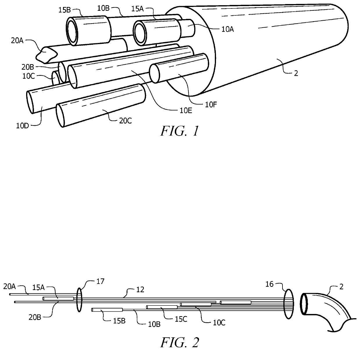
[0048]Sampling system 1 comprises a plurality of sampling well 10, designated 10A and 10B, with each sampling well terminating in a sampling mesh 15, such as sampling mesh 15A on a first end of sampling well 10A, sampling mesh 15B on a first end of sampling well 10B, and sampling mesh 15C on a first end of sampling well 10C. The sampling mesh covers a first end of the sampling well, designed to collect material from a matrix for sampling, and was formed of a corrugated and slotted sampling system, as described in U.S. application Ser. No. 15 / 066,811. Briefly, a corrugated conduit with a sampling channel formed from the removal of corrugation ribs was inserted over the sampling end of a sample well tube. The corrugated conduit was capped, and covered in a sieve. A grout spacer was disposed between sampling mesh 15A and sampling mesh 15B, preventing bleed over of analytes between the two sampling regions.

[0049]In preferred embodiments, sampling system 1 comprises a large numb...

Example

Example 2

[0050]Sampling system 1 was prepared by inserting a sampling mesh 15, formed of tubular mesh or corrugated filter as described in Example 1 with a 1.25-inch outer diameter, on a first end of a high density polypropylene tubing having a 0.5-inch OD and ⅜-inch ID. The tubes form a channel for sampling wells 10. This process was repeated with tubing of various lengths, such as each tube differing by 10 feet. The plurality of tubes were aligned with the second end of each tube aligned with the other tubes, as seen in FIG. 2. The longest tube was designated the anchor sampling well 12. The remaining tubes were tacked to anchor sampling well 12 at sample well tacking 16, forming a sampling well bundle. Methods of tacking the sampling wells to the anchor sampling well would be evident to one of skill in the art upon review of this disclosure. Non-limiting examples include adhesive tape, a pull line, pull ties, mill tape, liquid adhesives, screws, binding straps, or rope / twine.

[005...

Example

Example 3

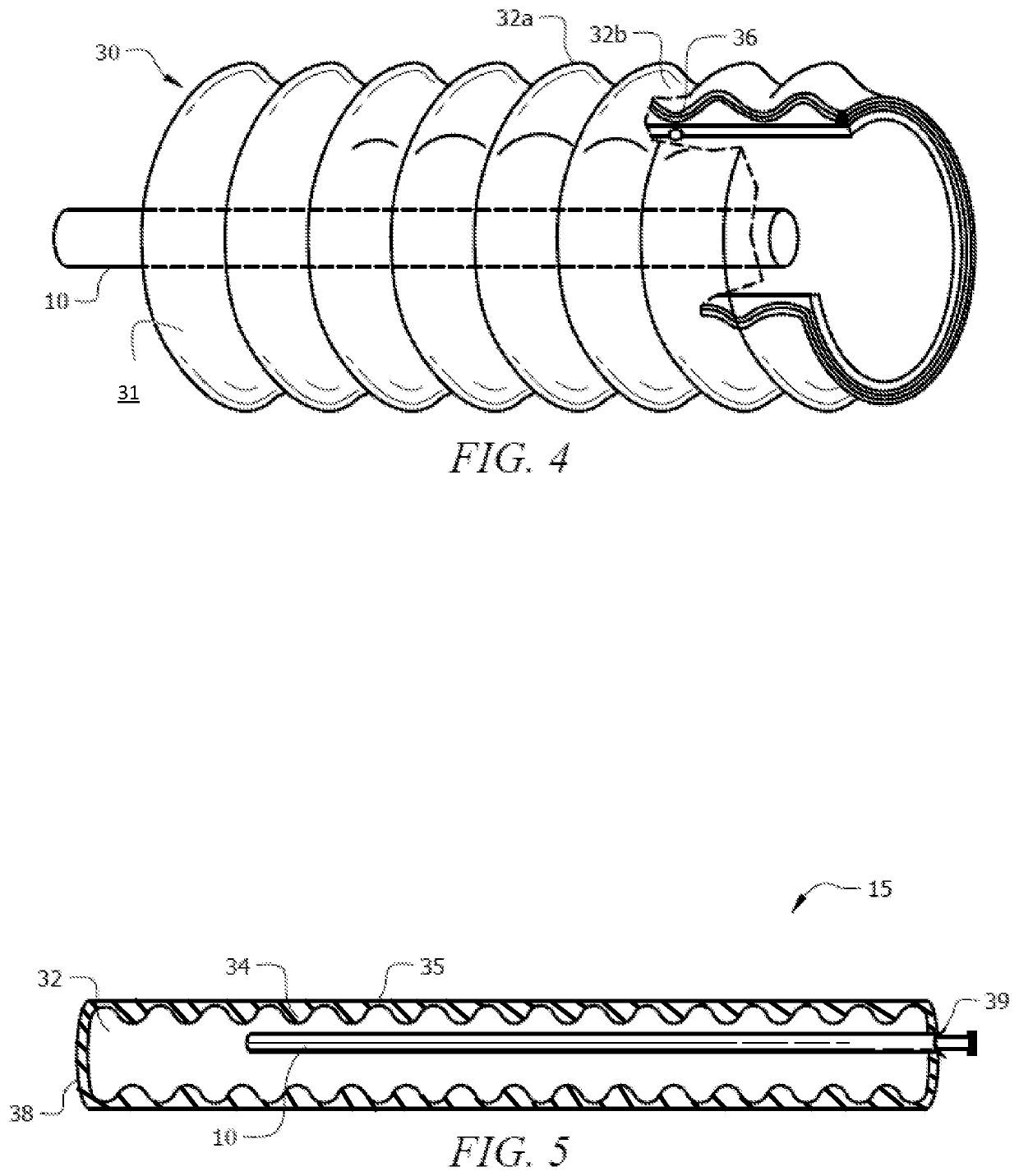
[0061]Sampling mesh 15 was optionally formed of corrugated conduit 30, which comprises a plurality of corrugated ridges formed of trough 34 and peak 35 disposed perpendicular to the longitudinal axis of corrugated conduit 30, as seen in FIG. 4. The corrugated conduit was formed of low density polyethylene (LDPE) tubing. Sample well tubing 40 ran parallel to the longitudinal axis of corrugated conduit 30, and terminates in the interior of corrugated conduit 30. Sampling channel 36 was formed on outer surface 31 of corrugated conduit 30 from the partial removal of the corrugated conduit, i.e. external rib 32b, while retaining the remainder of the corrugated conduit, i.e. internal rib 32a. As an example, a circular saw can be used to remove external rib 32b while retaining internal rib 32a, and allow the conduit's internal rib to collect liquids in the ground for matrix sampling or leak the fluid uniformly over the body length for remediation. The remaining portions of the ext...


PUM


Abstract

A device and method for collecting sample fluids from an underground source which includes sample wells terminating in a corrugated conduit and sieve. The sampling regions for each sample well is separated by a grout or expanding seal barrier. Negative pressure is optionally applied to extract fluids from the underground matrix for sampling. The device can also be used for remediating an environmental contaminant from soil or aquifers. Upon identification of at least one environmental contaminant, a remediation composition is injected into the soil or aquifer using the sampling wells of the device. The remediation fluids can be directed to specific locations by selectively utilizing one or more sampling wells to inject the remediation fluid.

Description

CROSS-REFERENCE TO RELATED APPLICATIONS[0001]This application is a continuation-in-part of currently pending U.S. patent application Ser. No. 15 / 066,811 entitled, “Corrugated and Slotted Injection System and Method of Use”, filed on Mar. 10, 2016, which claims priority to U.S. Provisional Patent Application No. 62 / 130,988 entitled, “Corrugated and Slotted Injection System and Method of Use”, filed Mar. 10, 2015, the contents of which are herein incorporated by reference.FIELD OF INVENTION[0002]This invention relates to remediation injection systems for in situ remediation of contaminated soil and / or ground water. More specifically, the invention provides a novel system having a slotted corrugated device for removing liquids and / or injecting chemicals and / or biological material into soil or water using for remediation of contaminated soil and / or ground water.BACKGROUND OF THE INVENTION[0003]Environmental testing has become increasingly important, especially in locations where manufac...

Claims


Application Information

Patent Timeline
IPC IPC(8): E21B49/02E21B43/30B09C1/00E21B49/08B09C1/02
CPCE21B43/305E21B49/08B09C1/00B09C2101/00B09C1/02
Inventor ROBINSON, LANCE I.PIATT, ERIK R.
Owner EN RX CHEM INC
Why Eureka
Try Eureka