Firearm attachable bullet trap

a technology of attachable bullet traps and bullets, which is applied in the field of rifles or light machine guns, can solve the problems of not being able to stop ball rounds, and achieve the effect of reducing velocity

Active Publication Date: 2010-11-11
COLT CANADA IP HLDG PARTNERSHIP
View PDF9 Cites 10 Cited by
  • Summary
  • Abstract
  • Description
  • Claims
  • Application Information

AI Technical Summary

Benefits of technology

[0016]In one embodiment the bullet trap having a gas escape connected to a bullet trap chamber, th...

Problems solved by technology

While the Compton device provides an essential function in allowing blank rounds, such as type C79A1 blank rounds, to be...

Method used


Image

  • Firearm attachable bullet trap
  • Firearm attachable bullet trap
  • Firearm attachable bullet trap

Examples


Embodiment Construction

[0026]Generally, the present invention provides a firearm attachable bullet trap for slowing, destructing, and preventing a bullet from exiting a rifle.

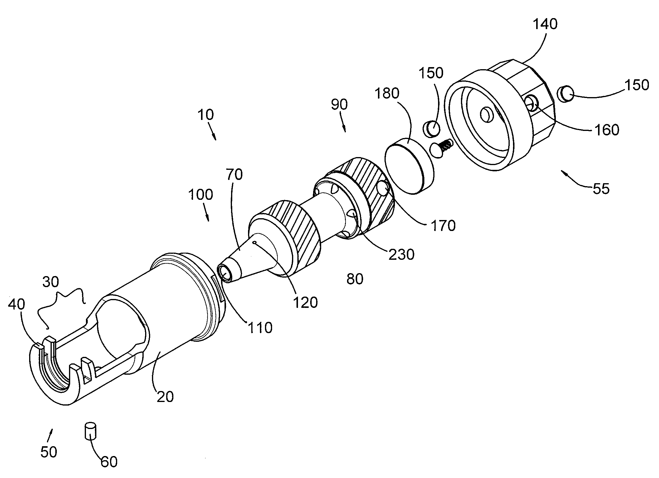
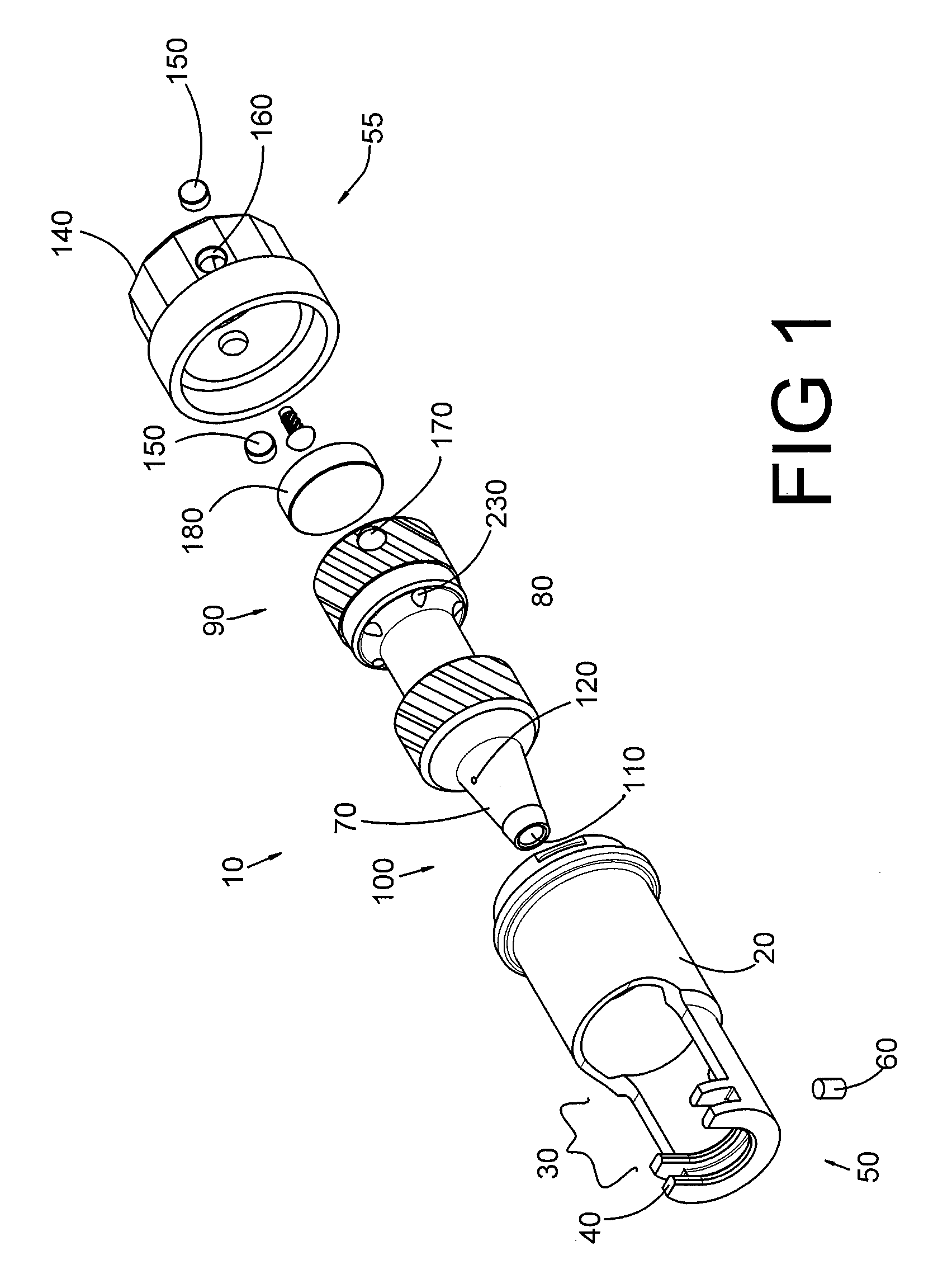
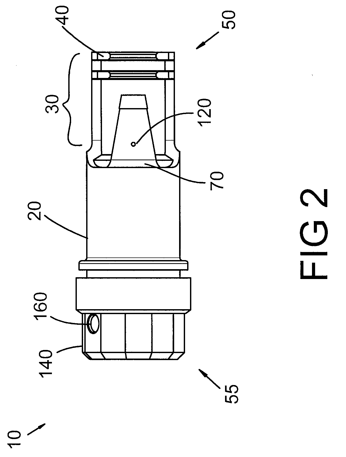
[0027]Referring to FIGS. 1-3, the firearm attachable bullet trap 10 includes a body 20 adapted to attach to a firearm 260 (see FIGS. 5-7). The body 20 has an attachment portion 30 with a flange 40 proximate a rear end 50 of the body 20, the flange 40 adapted to engage a compensator 270 (see FIGS. 6-7) to secure the firearm attachable bullet trap 10 to barrel 250. A set screw 60 provides for adjustment of the connection fit.

[0028]A spigot 70 is received within and attached to the body 20. Threads 80 may engage the body 20 to threadably secure the spigot 70 within the body 20. The spigot 70 has a front end 90, a rear end 100, and a reducing cross-section spigot bore 110 extending from the rear end 100 toward the front end 90. The spigot bore terminates at a solid end 115 near the front end 90 (see FIG. 4). The rear end 100 of the spigo...


PUM


Abstract

A firearm attachable bullet trap for use on a gas operated firearm having a compensator attached to the barrel. The bullet trap captures bullets from live rounds and provides an visual and tactile indication of live rounds having been fired. The bullet trap is designed for the shooting of blank rounds, but is adapted to handle live rounds having a bullet in a semi-automatic or automatic firearm.

Description

FIELD OF THE INVENTION[0001]The present invention relates generally to rifles or light machine guns. More particularly, the present invention relates to a firearm attachable bullet trap for stopping a bullet fired from a round in a rifle or light machine gun and dissipating the energy associated with the round.BACKGROUND OF THE INVENTION[0002]Canadian Patent 2,094,048 to Compton et al. (hereinafter Compton) teaches a blank firing attachment for use on a gas operated automatic rifle or light machine gun. The device restricts the exit of gases from the rifle barrel when a blank cartridge is filed, thus retaining sufficient gas pressure in the barrel to actuate the rifle's automatic firing mechanism and permit blank cartridges to be fired automatically or semi-automatically.[0003]While the Compton device provides an essential function in allowing blank rounds, such as type C79A1 blank rounds, to be fired automatically or semi-automatically, it is not designed to stop ball rounds, such ...

Claims


Application Information

Patent Timeline
IPC IPC(8): F41C27/00
CPCF41J13/00F41A21/32F41A21/26
Inventor ANDERSON, IAN JAMES
Owner COLT CANADA IP HLDG PARTNERSHIP
Why Eureka
Try Eureka