Drum Pad and Manufacturing Method Thereof

a technology of drum pads and manufacturing methods, applied in the field of drum pads, can solve the problems of musical performance hinderment, next trigger cannot be detected, error detection, etc., and achieve the effect of excellent percussion feeling

Active Publication Date: 2010-11-11
YAMAHA CORP
View PDF17 Cites 15 Cited by
  • Summary
  • Abstract
  • Description
  • Claims
  • Application Information

AI Technical Summary

Benefits of technology

[0013]The present invention provides a drum pad capable of providing an excellent percussion feeling and securely adhering a base portion to a body portion made of rubber, and provides a manufacturing method of the drum pad.
[0014]The present invention also provides a drum pad capable of suppressing a mechanical percussion sound and capable of enhancing the effect of damping a high-frequency vibration caused by the striking, thereby preventing erroneous sounding when a sound is sounded based on percussion detection.

Problems solved by technology

Accordingly, when a trigger for sounding a drum sound is detected from the detection signal representing a striking vibration, there is a fear that the trigger is erroneously detected twice or more while the striking vibration continues and that the next trigger cannot be detected if the pad portion is struck again before the preceding striking vibration does not attenuate.
Thus, a problem. is posed that the striking cannot be detected accurately, resulting in erroneous sounding.
The mechanical percussion sound, if excessively large, causes a problem that musical performance is hindered.
However, among raw materials of the body portion that provide a satisfactory percussion feeling, there are some that do not allow an adhesive to stick well, and therefore, actually usable materials are limited.
For example, ordinary adhesive does not properly stick to, e.g., a silicone-based rubber material.
Accordingly, it is difficult to adhere the base portion having, e.g., a metallic contact surface to the body portion made of silicone rubber material using adhesive, and therefore, a double-sided adhesive tape or an adhesive for silicone must be used, which results in increased cost.
In addition, it is difficult to ensure the required adhesion strength.

Method used


Image

  • Drum Pad and Manufacturing Method Thereof
  • Drum Pad and Manufacturing Method Thereof
  • Drum Pad and Manufacturing Method Thereof

Examples


Embodiment Construction

[0064]The present invention will now be described in detail below with reference to the drawings showing a preferred embodiment thereof.

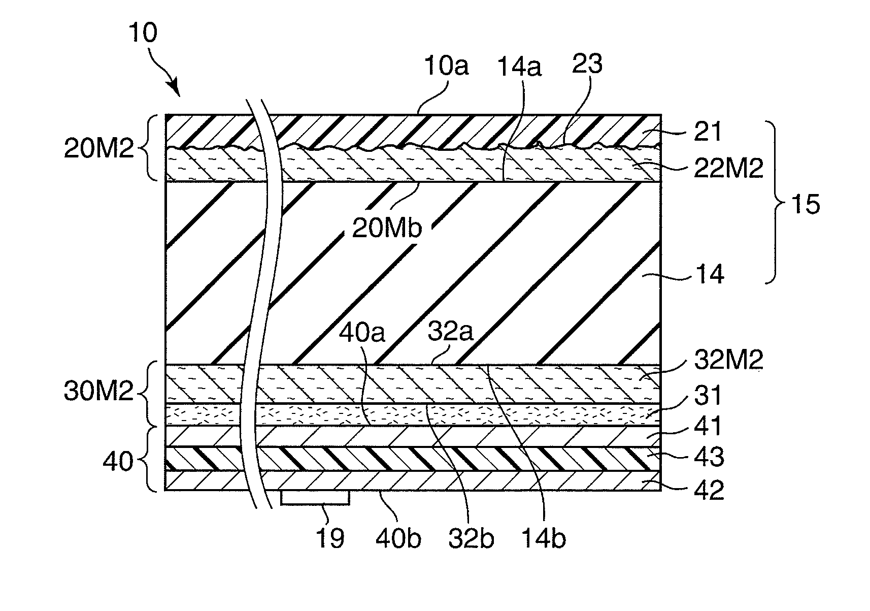
[0065]FIG. 1A schematically shows in perspective view a drum pad according to one embodiment of this invention. The drum pad shown at 10 in FIG. 1A is for use as, e.g., an electronic drum pad or a percussion input device for receiving percussion data to obtain sounding data, the drum pad 10 being adapted to be struck by a stick 11 or the like. The drum pad 10 is not, however, limited to these examples, and may be a pad for use as percussion practice, which is singly laid on a table or the like when used. The drum pad 10 is formed into, e.g., a disk-shape having a diameter φ of 260 mm and a thickness t of 20 mm for use in a 10 or 12 inch snare drum or tom although the shape, size, and intended use of the drum pad 10 are not limited thereto.

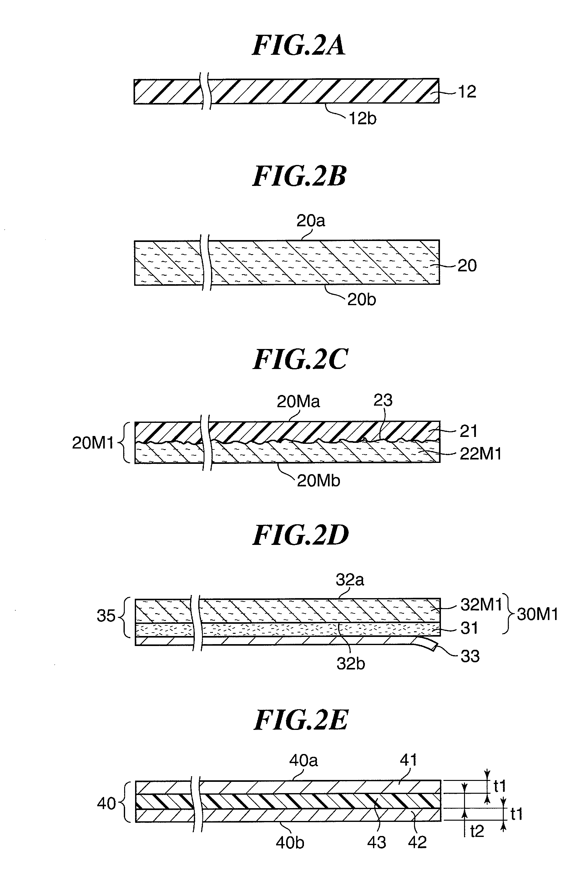
[0066]FIG. 1B schematically shows the construction of the drum pad 10 in cross section. For convenience of expla...


PUM

PropertyMeasurementUnit
thicknessaaaaaaaaaa
thicknessaaaaaaaaaa
thicknessaaaaaaaaaa

Abstract

A drum pad capable of providing an excellent percussion feeling and securely adhering a base portion to a body portion made of rubber. The drum pad has a rear-side clothlike material which is provided on a rear surface of the body portion and into which the rubber of the body portion is impregnated. The base portion is fixed to a rear surface of the rear-side clothlike material via a fixing layer made of pressure sensitive adhesive or adhesive and provided on the rear surface of the rear-side clothlike material.

Description

BACKGROUND OF THE INVENTION[0001]1. Field of the Invention[0002]The present invention relates to a drum pad for use as an electronic drum pad or a practice pad, and a manufacturing method of the same.[0003]2. Description of the Related Art[0004]Conventionally, a drum pad for use in an electronic drum or the like has been known, which generally has an elastic pad portion having a percussion surface, and a base portion provided on a rear side of the pad portion and mounted with a sensor for detecting the striking of the pad portion.[0005]For example, Japanese Laid-open Patent Publication No. 2005-227535 discloses an electronic drum pad, in which an iron plate as a base portion is fixed to a rear side of a pad portion, a sensor board made of resin is fixed to a rear surface of the iron plate, and a sensor is fixed to a rear surface of the sensor board.[0006]The sensor comprised of a piezoelectric device detects a variation conveyed from the pad portion being struck to the iron plate an...

Claims


Application Information

Patent Timeline
Patent Type & Authority Applications(United States)
IPC IPC(8): G10H3/00B32B37/24G10D13/02
CPCG10D13/029G10D13/024G10D13/26G10D13/02G10D13/03
Inventor HASHIMOTO, RYUJISAWADA, SHUICHINISHIDA, KENICHIHARADA, KEIZO
Owner YAMAHA CORP
Why Eureka
Try Eureka