System for determining the position of a piston along its path of travel for a fluid-dynamic actuator

a fluid-dynamic actuator and actuator technology, applied in the direction of measuring devices, instruments, using optical means, etc., can solve the problems of complex and expensive machining processes of sensor types, and achieve the effect of easy and inexpensive production, good level of precision

Active Publication Date: 2010-11-11
AMA SPA
View PDF6 Cites 4 Cited by
  • Summary
  • Abstract
  • Description
  • Claims
  • Application Information

AI Technical Summary

Benefits of technology

[0006]The purpose of the present invention is to provide a system for determining the position of a piston along its path of travel in a cylinder for a double-acting fluid-dynamic actuator, which achieves a good level of precision, overcomes the drawbacks described above and is, at the same time, easy and inexpensive to produce.

Problems solved by technology

This type of sensor requires complex and expensive machining processes to produce both the cylinder and the rod of the piston.

Method used


Image

  • System for determining the position of a piston along its path of travel for a fluid-dynamic actuator
  • System for determining the position of a piston along its path of travel for a fluid-dynamic actuator

Examples


Embodiment Construction

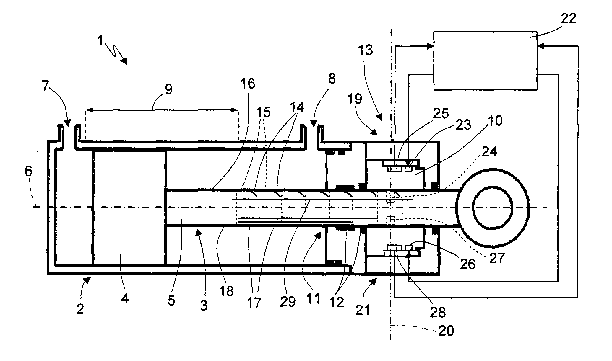
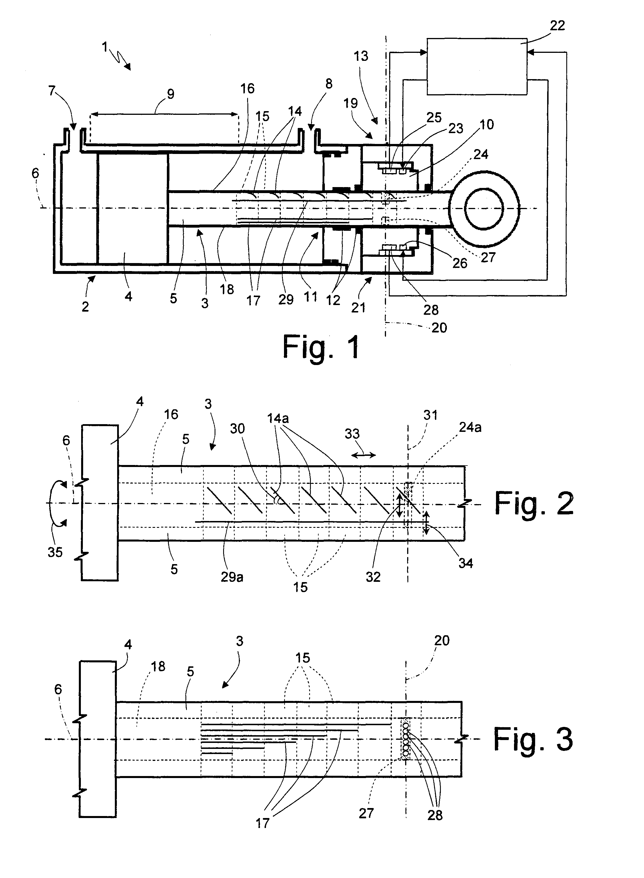
[0012]FIG. 1 is a partial longitudinal cross-sectional view of a double-acting fluid-dynamic actuator 1 comprising a cylinder 2 and a piston 3 movable inside the cylinder 2 under the action of a pressurized fluid (not illustrated). The piston 3 comprises a head 4 sealingly slidable along the internal walls of the cylinder 2 and a rod 5 integral with the head 4 and having a longitudinal axis 6, along which the cross-sectional view of FIG. 1 is defined. The cylinder 2 is provided with two apertures, a first of which is indicated by number 7 and allows the fluid to flow into and out of the cylinder 2 above the head 4, and a second of which is indicated by number 8 and allows the fluid to flow into and out of the cylinder 2 below the head 4, that is from the part with the rod 5. The piston 3 is movable along a rectilinear path of travel, which is indicated by number 9 and extends substantially between the apertures 7 and 8 parallel to the axis 6.

[0013]The actuator 1 also comprises a cha...


PUM


Abstract

A system (13) for determining the position of a piston (3) along its path of travel (9) in a cylinder (2) of a fluid-dynamic actuator (1), wherein the surface of the rod (5) of the piston (3) is provided with first grooves (14) machined on respective sections (15) of the rod (5), so that projections of the first grooves (14) onto a first plane parallel to the rod axis (6) define segments (14a) arranged obliquely with respect to the axis (6), and second grooves (17) extending parallel to the axis (6) for respective lengths such that a respective number of second grooves (17) run across each section (15), optical sensors (19, 21) detect the presence of second grooves (17) through a second plane (20) transversal to the axis (6) and a displacement (32) of segments (14a) along a line (31) coplanar with the second plane (20) due to a movement of the piston (3), and a processing unit (22) counts the detected second grooves (17) and determines the position of the piston (3) as a function of the count of second grooves (17) and the displacement (32) of segments (14a).

Description

TECHNICAL FIELD[0001]The present invention relates to a system for determining the position of a piston along its path of travel in a cylinder for a fluid-dynamic actuator.[0002]In particular, the present invention is advantageously, but not exclusively applicable to a double-acting fluid-dynamic actuator, to which the following description specifically refers but without any loss of generality.BACKGROUND ART[0003]A double-acting fluid-dynamic actuator comprises a cylinder and a piston, which is movable inside the cylinder under the action of a pressurized fluid and is provided with a head that sealingly slides along the inside walls of the cylinder and a rod integral with the head.[0004]A system for determining the position of a piston along its path of travel for a fluid-dynamic actuator of the type described above is known in the prior art. Said system normally comprises a magnetostrictive sensor suitable to be mounted with a first part on the rod and with a second part on the cy...

Claims


Application Information

Patent Timeline
Patent Type & Authority Applications(United States)
IPC IPC(8): F01B31/12
CPCF15B15/2846G01B11/14G01B11/024F15B15/2876
Inventor CANI, PAOLOREGGIANI, WAINER
Owner AMA SPA
Why Eureka
Try Eureka