Flywheel generator system having open shaped loop coils

Inactive Publication Date: 2010-11-11
SURODIN EDUARD G
View PDF11 Cites 6 Cited by
  • Summary
  • Abstract
  • Description
  • Claims
  • Application Information

AI Technical Summary

Benefits of technology

[0018]An object of the present invention is to provide a flywheel generator system and method of generating electricity which conserves electric energy by the use of a series of C-shaped or other shape looped coils positioned around a flywheel with magnets extending from the outer edge of the flywheel passing through the coils to generate electricity and with no magnetic material is the coils there is no resistance created thereby providing more efficient electricity generation.
[0020]An advantage of the C-coil (C-shaped coil or semicircular coil) of the present invention is that it doesn't have any magnetic material inside the coil and has a special type of coil winding to allow magnets to pass through the winding of the C-coil itself, and because there is no magnetic material at all, so there is no magnetic resistance at all, so that the magnets to go through the C-coils freely, and electro magnetic induction from the magnets makes the windings of each of the C-coils to produce electric current.

Problems solved by technology

The problem with prior art electric generators is that a rotor with permanent or electric magnets is attracted by magnetic material inside of the coils of the stator to make the rotor spin inside the stator with high magnetic resistance.

Method used


Image

  • Flywheel generator system having open shaped loop coils
  • Flywheel generator system having open shaped loop coils
  • Flywheel generator system having open shaped loop coils

Examples


Embodiment Construction

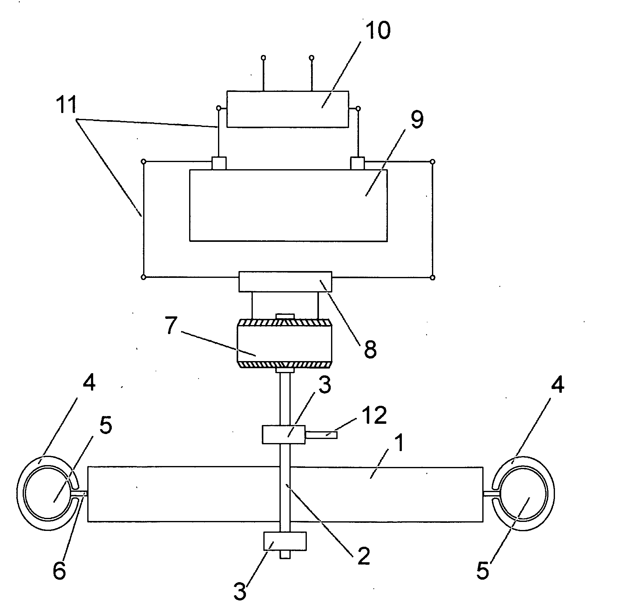
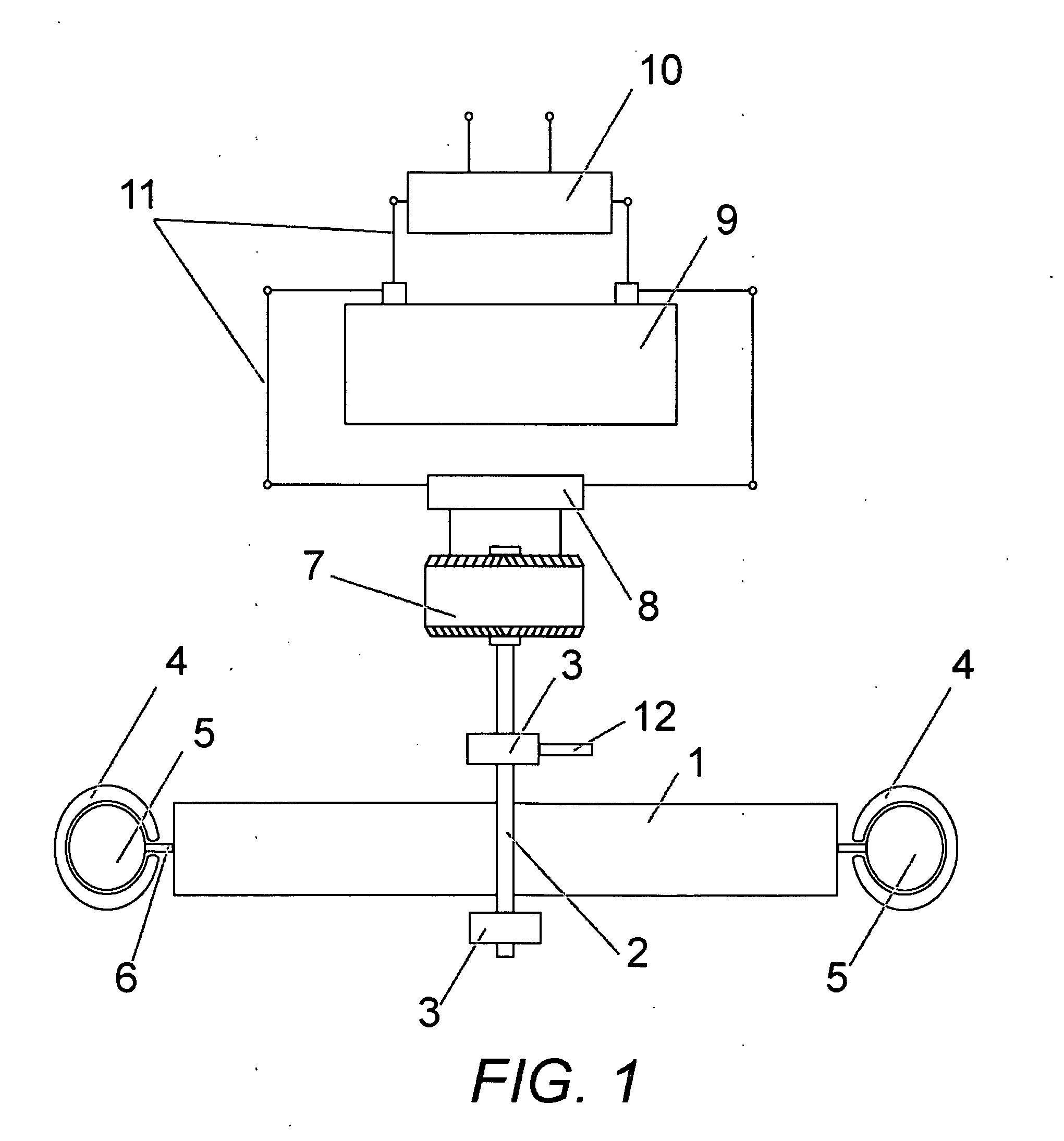
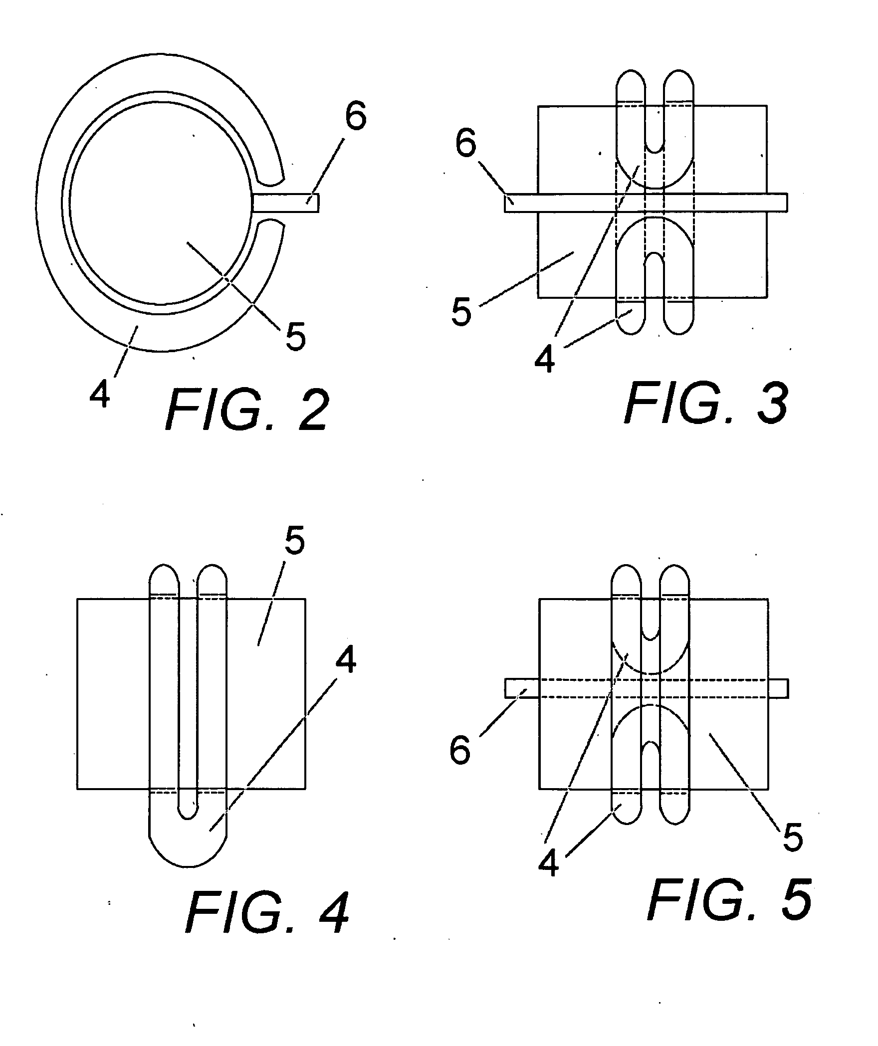
[0030]In FIGS. 1-8, a flywheel electric generator system 20 uses loop shaped coils 4 encircling a spinning flywheel 1 so that a series of mating shaped permanent magnets 5 attached to a disc 6 extending from the outer perimeter of the flywheel 1 with the shaped magnets 5 passing through the mating shaped coil openings 17 and 17A to generate electricity in the coils.

[0031]In FIGS. 1 and 6. the flywheel 1 for the flywheel electric generator system 20 comprises a flywheel 1 of substantial mass and thickness pivoting about a center axis 2. A thin annular disc 6 extends outwardly from an outer perimeter of the flywheel 1. The annular disc 6 has a thickness substantially less than the flywheel. A series of magnets 5 attached to an outer perimeter of the annular disc 6. The magnets 5 each having a mating identical peripheral shape. A source of rotational power causes the flywheel 1 to spin.

[0032]In FIGS. 2-5, 7 and 8, a series of coil loops 4 are attached to a structure separate from the f...


PUM


Abstract

A series of elongated oval wire windings bent into open C-shaped or other loop shape coils are positioned around a flywheel. Magnets, mating the loop opening shape, extend from the outer edge of the flywheel on a thin disc to pass through the coils to generate electricity with the spin of the flywheel. With no magnetic material is the coils there is no magnetic resistance created thereby providing more efficient electricity generation.

Description

CROSS-REFERENCE TO RELATED APPLICATIONS[0001]Not Applicable.STATEMENT REGARDING FEDERALLY SPONSORED RESEARCH OR DEVELOPMENT[0002]Not Applicable.THE NAMES OF THE PARTIES TO A JOINT RESEARCH OR DEVELOPMENT[0003]Not Applicable.BACKGROUND OF THE INVENTION[0004]1. Field of the Invention[0005]The present invention relates generally to power generation devices, and in particular to a flywheel generator system and method of generating electricity which conserves electric energy by the use of a series of C-shaped or other shape looped coils positioned around a flywheel with magnets extending from the outer edge of the flywheel passing through the coils to generate electricity and with no magnetic material is the coils there is no resistance created thereby providing more efficient electricity generation.[0006]2. Description of Related Art including information disclosed under 37 CFR 1.97 and 1.98[0007]As is known in the prior art, electric generator methods of energy production are based on ...

Claims


Application Information

Patent Timeline
IPC IPC(8): H02K3/04H02K53/00
CPCY02E60/16H02K7/025
Inventor SURODIN, EDUARD G.
Owner SURODIN EDUARD G
Why Eureka
Try Eureka