Eureka AIR delivers breakthrough ideas for toughest innovation challenges, trusted by R&D personnel around the world.

Resistive touch panel

a technology of resistive touch and touch panel, which is applied in the field can solve the problems of increasing production cost and further affecting the operating performance and achieve the effect of reducing the manufacturing step and improving the yield of resistive touch panel

Inactive Publication Date: 2010-11-11
MINLEAD
View PDF6 Cites 19 Cited by
  • Summary
  • Abstract
  • Description
  • Claims
  • Application Information

AI Technical Summary

Benefits of technology

[0010]The main objective of the present invention is to provide a resistive touch panel, which gets rid off the mounting of the solid film and eliminates the fabricating step for bonding with the solid film, thereby improving yield of the resistive touch panel.
[0014]A resistive touch panel is formed by bonding the upper panel module and the lower panel module. Such structure can effectively reduce component quantity of the touch panel. As such, production costs are lowered to improve competitive edge in the market. Moreover, steps for fabricating the resistive touch panel can be further simplified to enhance yield.

Problems solved by technology

Therefore, an uneven surface of the resistive touch panel easily occurs and further affects the operating performance of the resistive touch panel.
Once the uneven issue occurs, the defective goods must be rejected causing an increase in production cost.

Method used


Image

  • Resistive touch panel
  • Resistive touch panel
  • Resistive touch panel

Examples


Embodiment Construction

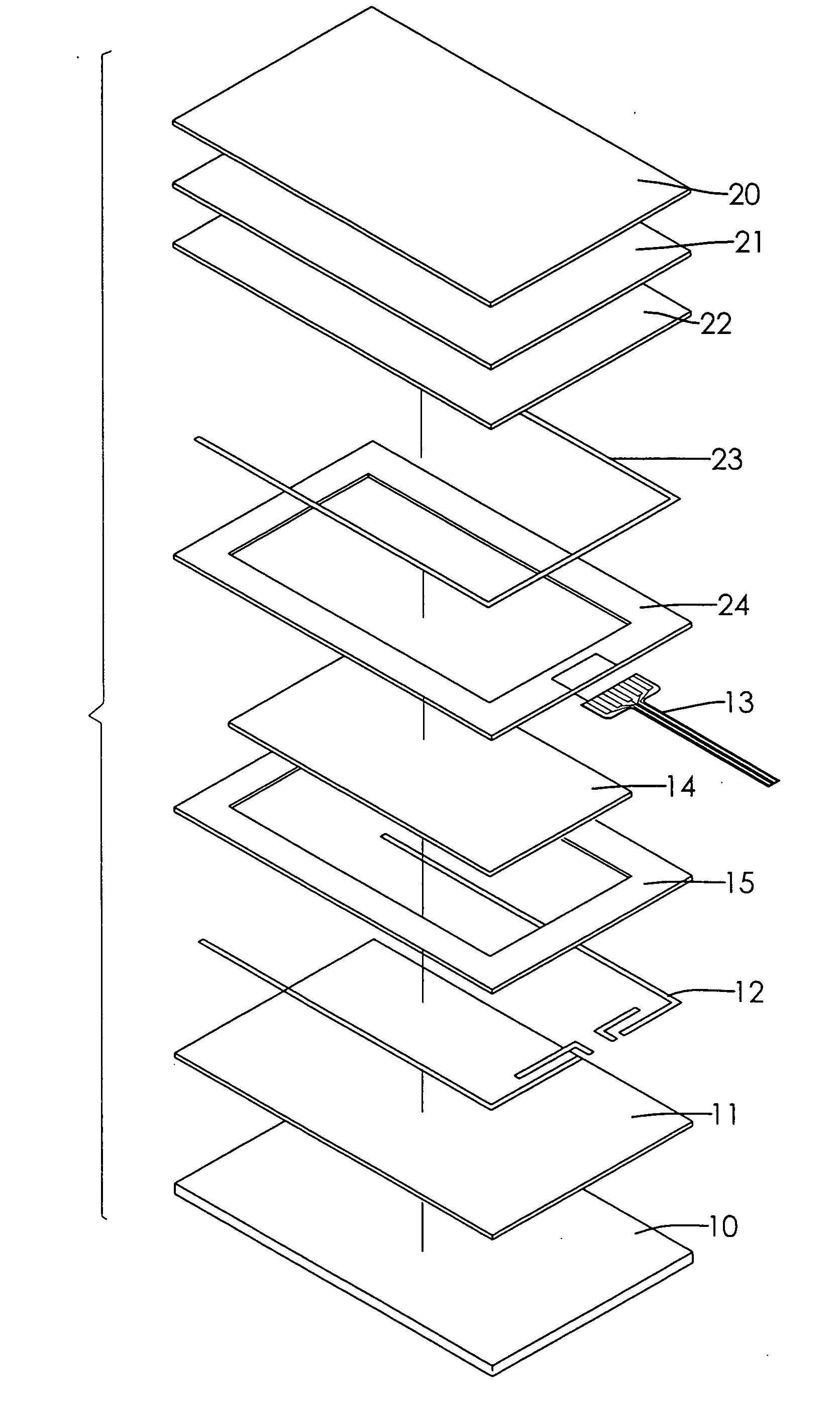
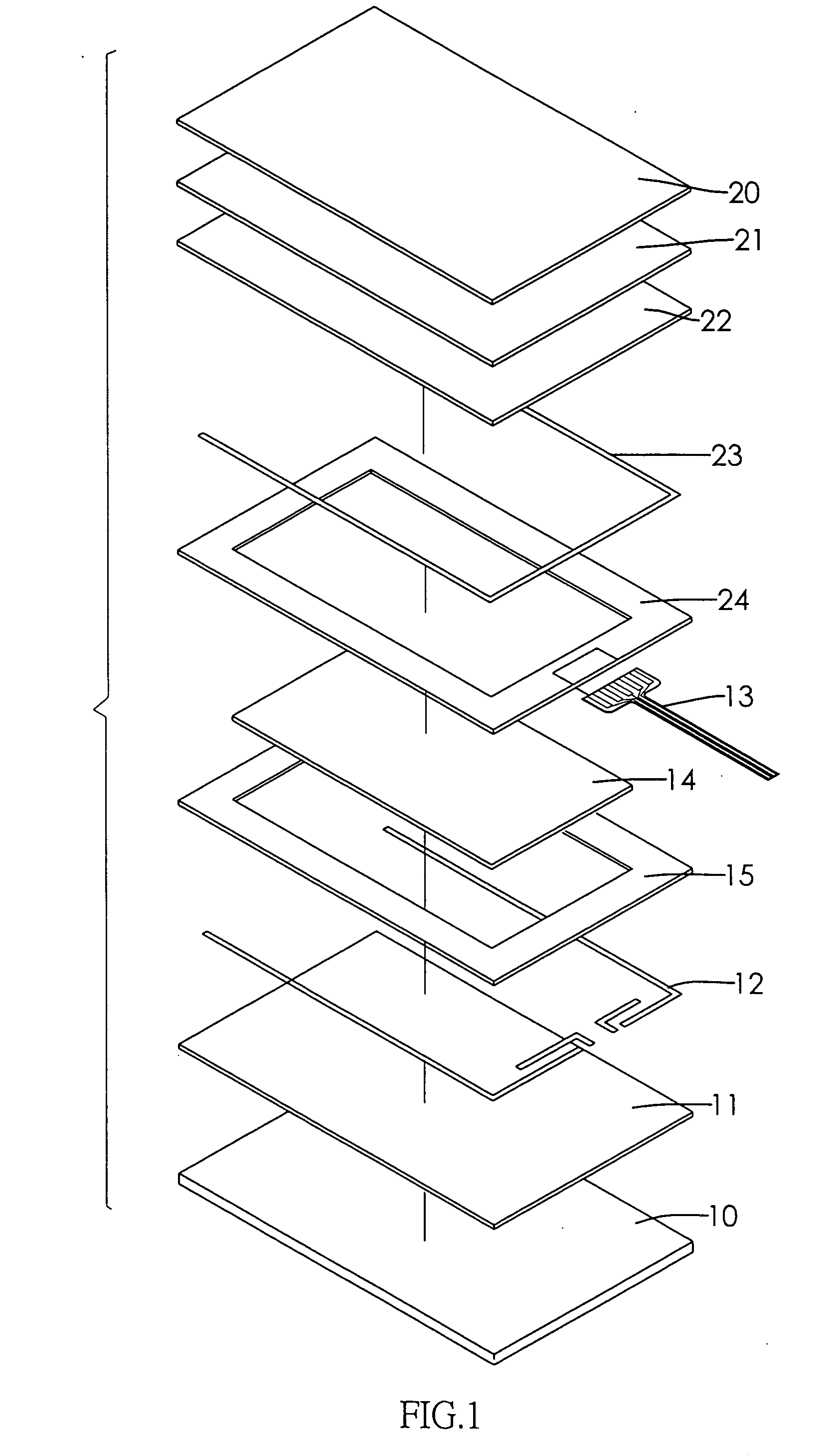
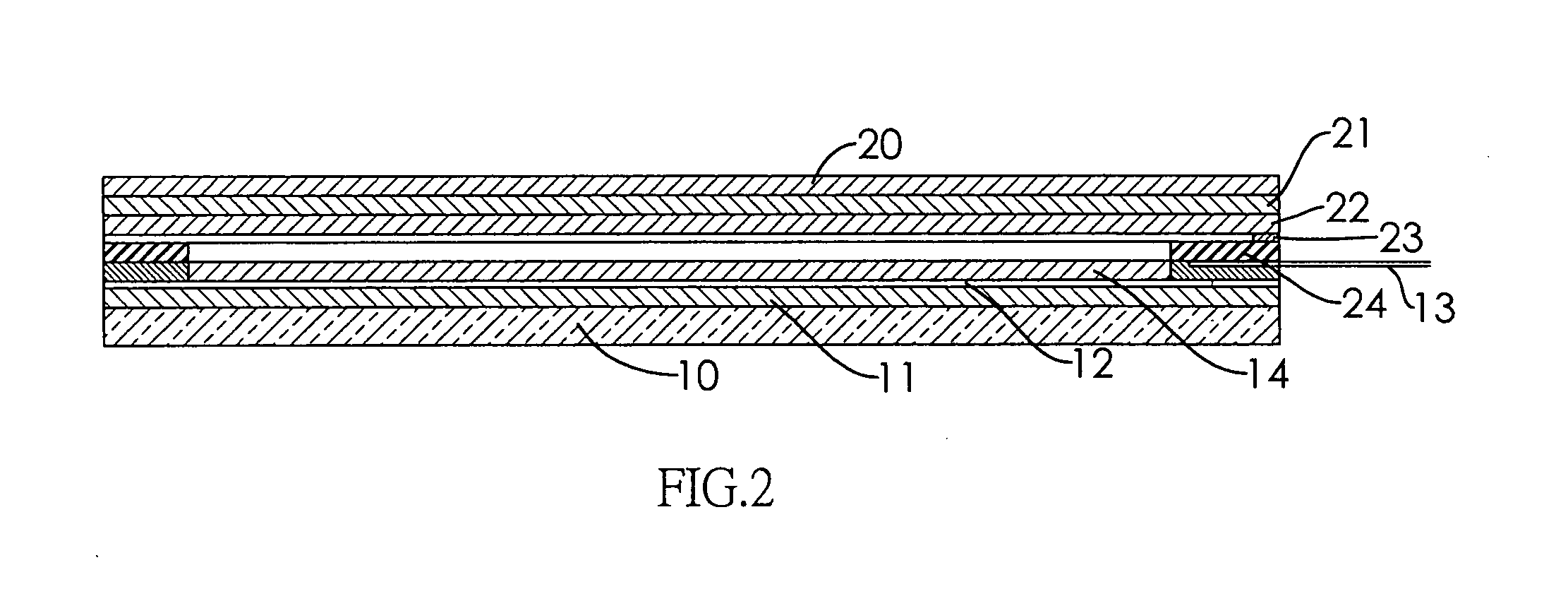
[0023]With reference to FIG. 1 and FIG. 2, a resistive touch panel in accordance with the present invention has an upper panel module, a lower panel module, an adhesive layer (15), a separating layer (14) and a flexible circuit board (13).

[0024]The lower panel module is mounted on the upper panel module through the adhesive layer (15). The lower panel module has a substrate (10), a lower conducting layer (11) and a plurality of electrodes (12). The substrate (10) is transparent and has a top surface. The lower conducting layer (11) is formed on the top surface of the substrate (10). The electrodes (12) are mounted on edges of a top surface of the lower conducting layer (11). The flexible circuit board (13) has a plurality of terminals. One end of each of the terminals of the flexible circuit board (13) is electronically connected with the corresponding electrode (12) of the lower conducting layer (11), and the other end of each of the terminals of the flexible circuit board (13) is ...


PUM


Abstract

A resistive touch panel has a lower panel module and an upper panel module, an adhesive layer, a separating layer and a flexible circuit board. The lower panel module has a substrate, a lower conducting layer and a plurality of electrodes. The upper panel module has a protective film, an upper conducting layer, a pattern layer, an ink electrode mounted to electrically connect with the flexible circuit board, and an insulation layer. One end of the flexible circuit board and the separating layer are sandwiched between the top surface of the lower conducting layer and the top surface of the upper conducting layer. Given the foregoing structure, the components and steps for fabricating the resistive touch panel can be reduced since the pattern layer is directly printed on the bottom surface of the upper conducting layer. Therefore, fabricating yields are increased.

Description

BACKGROUND OF THE INVENTION[0001]1. Field of the Invention[0002]The present invention relates to a resistive touch panel, and more particularly to a panel structure facilitating assembly and enhancing yield of a resistive touch panel.[0003]2. Description of the Related Art[0004]Recent technology trends have been toward touch screen devices using touch panels, which are either resistive touch panels or capacitive touch panels. The resistive touch panel for an electronic device, as shown in FIG. 6 and FIG. 7, has a bottom panel, a top panel, a first adhesive layer (904), a separating layer (905), a flexible circuit board (903), a solid film (92), a second adhesive layer (921) and a pattern layer.[0005]The separating layer (905) and one end of the flexible circuit board (903) are sandwiched between the bottom and top panels by the first adhesive layer (904).[0006]The bottom panel has a substrate (90), a lower conducting layer (901) and a plurality of first electrodes (902). The lower c...

Claims


Application Information

Patent Timeline
IPC IPC(8): G06F3/045
CPCG06F3/045G02F1/13338G06F3/041G06F2203/04103G06F2203/04113
Inventor HSIH, LUNG-SHENG
Owner MINLEAD
Why Eureka
Eureka Blog
Learn More