Display device having optical sensors

a display device and optical sensor technology, applied in the field of display devices, can solve the problems of difficult to distinguish between shadow images and background, touch positions may not be able to be detected properly, etc., and achieve the effects of high accuracy, simplified device configuration, and high accuracy

Inactive Publication Date: 2010-11-11
SHARP KK
View PDF25 Cites 54 Cited by
  • Summary
  • Abstract
  • Description
  • Claims
  • Application Information

AI Technical Summary

Benefits of technology

[0016]According to the first aspect of the present invention, since a filter portion that allows infrared light to pass therethrough and cuts off visible light is provided in path of light entering the optical sensor, an image obtained by the optical sensors is not influenced by visible light included in outside light which does not include infrared light (e.g., light from a fluorescent lamp and the like), or included in backlight light reflected off an object present in the vicinity of the display surface. Accordingly, a touch position can be detected with high accuracy, based on an image that is not influenced by visible light included in a large amount in outside light or backlight light.
[0017]According to the second aspect of the present invention, by forming the filter portion in the color filter, the configuration of the device can be simplified. In addition, the light reception sensitivity of the optical sensors formed of polysilicon is lower for red light than for green light and blue light. Therefore, by forming the filter portion within the red color filter, even when visible light enters an optical sensor in an oblique direction without passing through a filter portion, the influence of the entered visible light on an image obtained by the optical sensors is reduced, enabling to detect a touch position with high accuracy.
[0018]According to the third aspect of the present invention, by arranging the filter portion in a position within a red color filter and adjacent to the light-shielding film that cuts off visible light, even when visible light enters an optical sensor in an oblique direction without passing through a filter portion, the influence of the entered visible light on an image obtained by the optical sensors is further reduced, enabling to detect a touch position with higher accuracy.
[0019]According to the fourth aspect of the present invention, by forming the filter portion and the color filter separately, the filter portion can be implemented in various forms. In addition, the light reception sensitivity of the optical sensors formed of polysilicon is lower for red light than for green light and blue light. Thus, by arranging the filter portion in a position in which the filter portion overlaps a red color filter when viewed in a direction perpendicular to the filter portion, even when visible light enters an optical sensor in an oblique direction without passing through a filter portion, the influence of the entered visible light on an image obtained by the optical sensors is reduced, enabling to detect a touch position with high accuracy.
[0020]According to the fifth aspect of the present invention, by arranging the filter portion in a position in which the filter portion overlaps a red color filter when viewed in a direction perpendicular to the filter portion and which is adjacent to the light-shielding film that cuts off visible light, even when visible light enters an optical sensor in an oblique direction without passing through a filter portion, the influence of the entered visible light on an image obtained by the optical sensors is further reduced, enabling to detect a touch position with higher accuracy.
[0021]According to the sixth aspect of the present invention, the filter portion that allows infrared light to pass therethrough and cuts off visible light can be easily formed using a resin filter.

Problems solved by technology

In the method of detecting a shadow image, when the illumination of outside light is low (the surroundings are dark), it becomes difficult to distinguish between a shadow image and a background in an image obtained by the optical sensors and accordingly a touch position may not be able to be detected properly.

Method used


Image

  • Display device having optical sensors
  • Display device having optical sensors
  • Display device having optical sensors

Examples


first embodiment

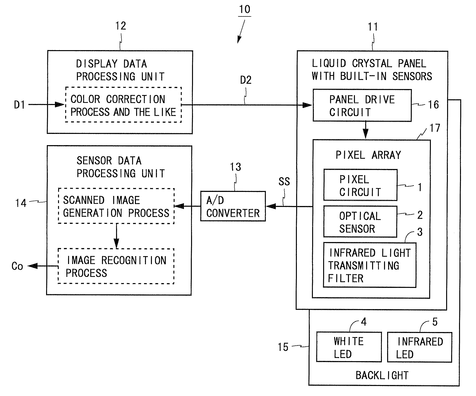
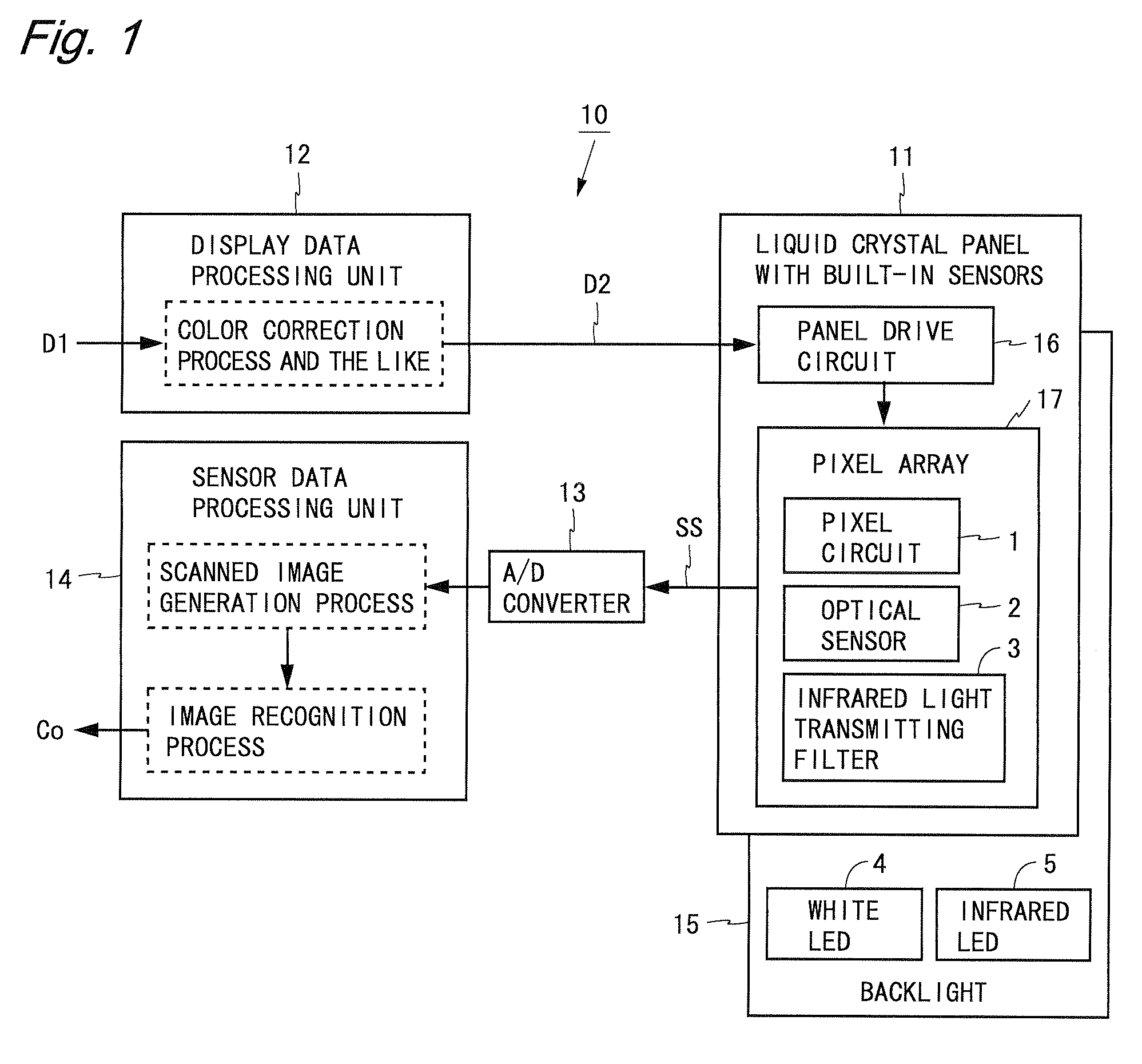
[0070]FIG. 1 is a block diagram showing a configuration of a liquid crystal display device according to a first embodiment of the present invention. A liquid crystal display device 10 shown in FIG. 1 includes a liquid crystal panel with built-in sensors 11, a display data processing unit 12, an A / D converter 13, a sensor data processing unit 14, and a backlight 15. The liquid crystal panel with built-in sensors 11 (hereinafter, referred to as the liquid crystal panel 11) includes a panel drive circuit 16 and a pixel array 17. The pixel array 17 includes a plurality of pixel circuits 1 and a plurality of optical sensors 2 which are arranged two-dimensionally. Each optical sensor 2 is provided with an infrared light transmitting filter 3 that allows infrared light to pass therethrough and cuts off (absorbs) visible light.

[0071]Display data D1 is inputted to the liquid crystal display device 10 from an external source. The display data processing unit 12 performs, if necessary, a color...

second embodiment

[0103]FIG. 11 is a block diagram showing a configuration of a liquid crystal display device according to a second embodiment of the present invention. A liquid crystal display device 60 shown in FIG. 11 is such that in the liquid crystal display device 10 according to the first embodiment the liquid crystal panel with built-in sensors 11 is replaced by a liquid crystal panel with built-in sensors 61. Of the components in the present embodiment, the same components as those in the first embodiment are denoted by the same reference numerals and description thereof is omitted.

[0104]The liquid crystal panel with built-in sensors 61 (hereinafter, referred to as the liquid crystal panel 61) includes a panel drive circuit 16 and a pixel array 62. The pixel array 62 includes a plurality of pixel circuits 1 and a plurality of optical sensors 2 which are arranged two-dimensionally. The pixel array 62 further includes an infrared light transmitting and light-shielding film 6 that allows infrar...


PUM


Abstract

A liquid crystal panel with built-in sensors 11 includes, in a pixel array 17, a plurality of pixel circuits 1 and a plurality of optical sensors 2 which are arranged two-dimensionally. Infrared light transmitting filters 3 that allow infrared light to pass therethrough and cut off visible light are respectively provided in paths of light entering the optical sensors 2. Accordingly, an image obtained by the optical sensors 2 is prevented from being influenced by visible light included in outside light or backlight light and thus a touch position is detected with high accuracy, based on an image that is not influenced by visible light included in a large amount in outside light or backlight light. Instead of the infrared light transmitting filters 3, a light-shielding film having the same property 3 may be used.

Description

TECHNICAL FIELD[0001]The present invention relates to a display device and more particularly to a display device having a plurality of optical sensors provided in a display panel.BACKGROUND ART[0002]In recent years, electronic devices that can be operated by touching a screen with a finger, a pen, or the like, have proliferated. In addition, for a method of detecting a touch position on a display screen, a method is known in which a plurality of optical sensors are provided in a display panel and a shadow image which is created when a finger or the like approaches a screen is detected using the optical sensors. In the method of detecting a shadow image, when the illumination of outside light is low (the surroundings are dark), it becomes difficult to distinguish between a shadow image and a background in an image obtained by the optical sensors and accordingly a touch position may not be able to be detected properly. In view of the above, for display devices including a backlight, a...

Claims


Application Information

Patent Timeline
Patent Type & Authority Applications(United States)
IPC IPC(8): G06F3/042
CPCG02F1/13338G02F1/133512G02F2001/13312G06F3/042G02F2203/11G06F3/0412G02F2202/104G02F1/13312
Inventor GOTOH, TOSHIMITSUFUJIOKA, AKIZUMIKUBOTA, AKINORIOYOBE, KEI
Owner SHARP KK
Why Eureka
Try Eureka