Eureka AIR delivers breakthrough ideas for toughest innovation challenges, trusted by R&D personnel around the world.

Fluid ejecting apparatus

Active Publication Date: 2010-11-11
SEIKO EPSON CORP
View PDF7 Cites 7 Cited by
  • Summary
  • Abstract
  • Description
  • Claims
  • Application Information

AI Technical Summary

Benefits of technology

[0009]An advantage of some aspects of the invention is to provide a fluid ejecting apparatus that is capable of reducing the burden of a negative pressure generating section. In addition to such load reduction, the fluid ejecting apparatus prevents misty fluid, which is some part of fluid that has been ejected from a fluid ejecting head as waste fluid into a fluid catching section for flushing and has formed into mist particles or the like, from floating out of the fluid catching section.

Problems solved by technology

In such a case, there is a risk that the ink-ejection performance of a printer might deteriorate.
For this reason, the disclosed printer has a disadvantage in that the burden of the negative pressure generating means is inevitably heavy because it requires extra power due to and corresponding to the greater suction amount of air entering the fluid catching unit through the opening, which is a problem that remains to be solved.
In addition, the internal pressure of the fluid catching section becomes negative due to the operation of the negative pressure generating section during non-flushing operation.
Therefore, the negative pressure generating section does not operate when the cover member is moved from the cover position to the retracted position to open the opening of the fluid catching section.

Method used


Image

  • Fluid ejecting apparatus
  • Fluid ejecting apparatus
  • Fluid ejecting apparatus

Examples


Embodiment Construction

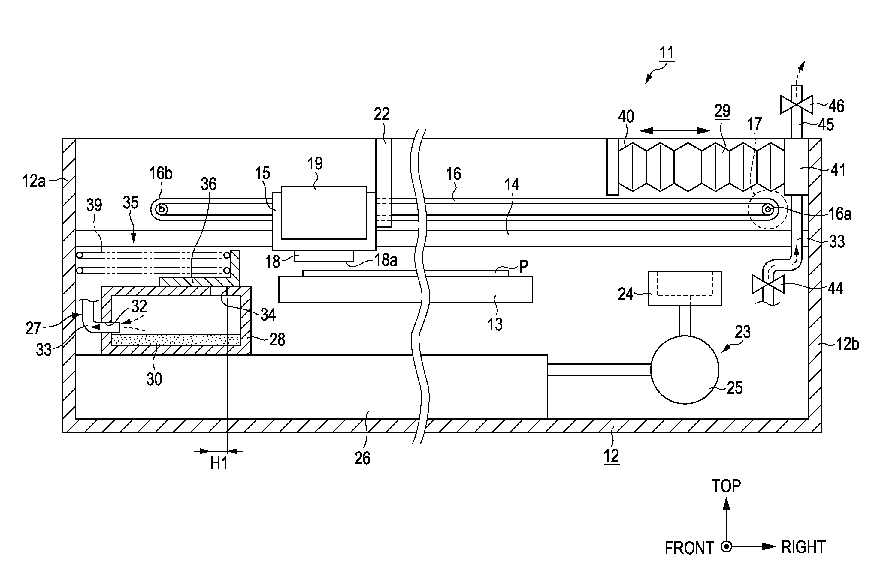
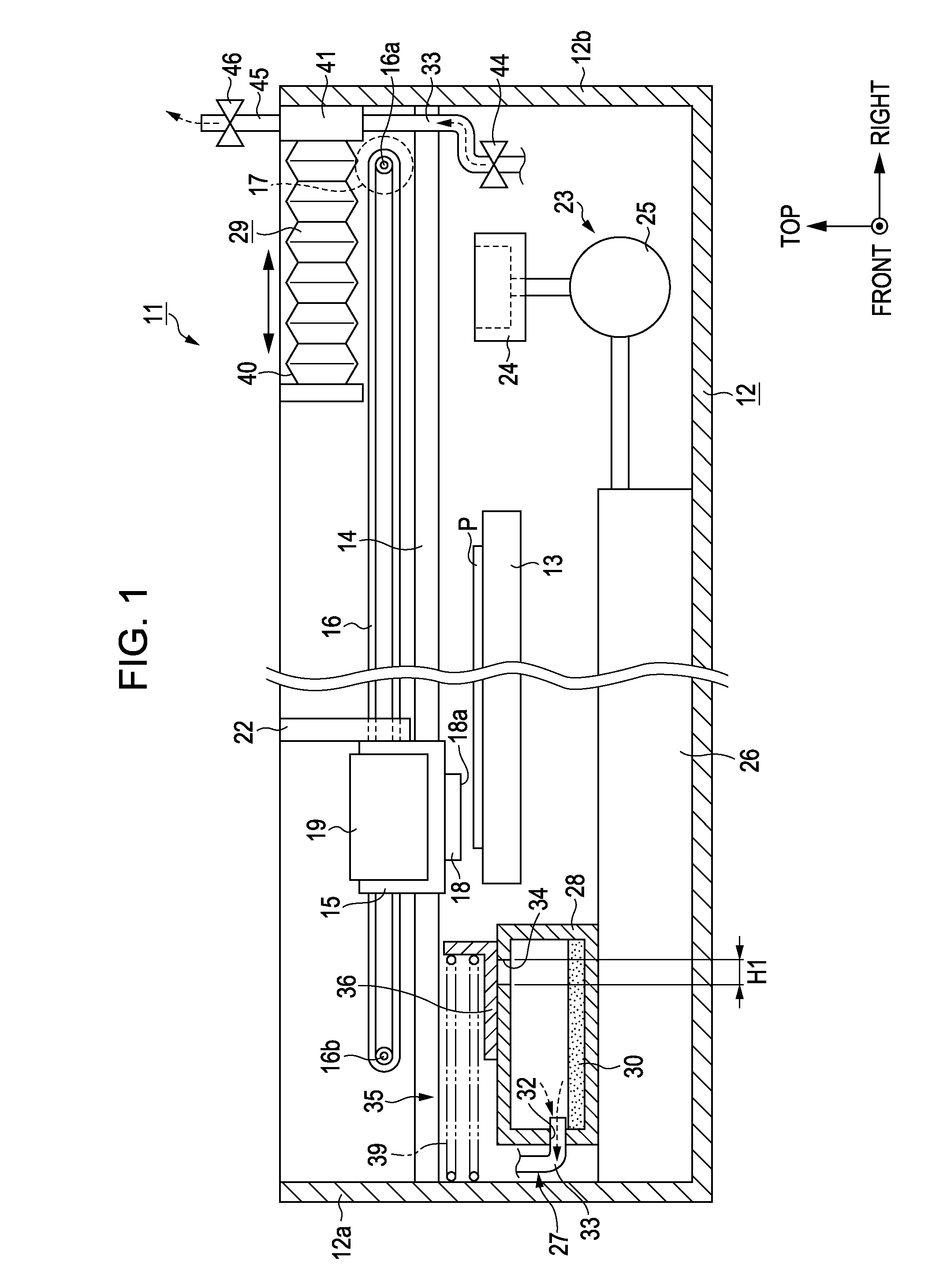
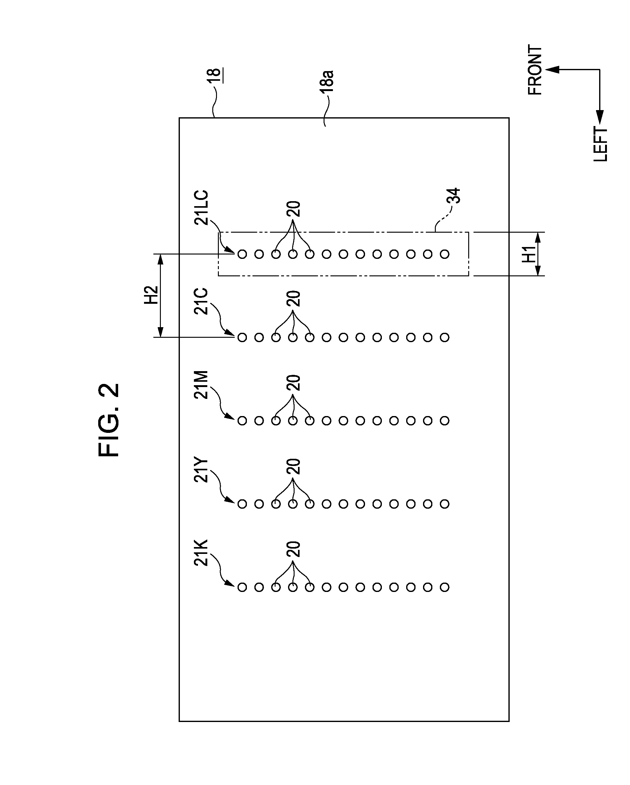
[0028]With reference to FIGS. 1 to 5, an ink-jet printer according to an exemplary embodiment of the invention will now be explained in detail. The ink-jet printer described below is a kind of a fluid ejecting apparatus according to an aspect of the invention. Note that the terms “anteroposterior direction” (e.g., “from-back-to-front” direction or, when viewed in the reverse orientation, “from-front-to-back” direction), “horizontal direction”, and “vertical direction” that appear in the following description of this specification mean the forward / backward (front / back) direction, the leftward / rightward (left / right) direction, and the upward / downward (top / bottom) direction shown by arrows in FIG. 1, respectively. The “from-back-to-front” direction corresponds to the sub scan direction. The horizontal direction corresponds to the main scan direction.

[0029]As illustrated in FIG. 1, an ink-jet printer 11 according to the present embodiment of the invention is provided with a frame 12, wh...


PUM


Abstract

A fluid ejecting apparatus includes a fluid ejecting head that has a nozzle formation surface and ejects fluid from a nozzle formed as a hole through the nozzle formation surface. A fluid catching unit has an opening that faces the nozzle formation surface of the fluid ejecting head at the time of flushing, as waste fluid is ejected from the nozzle of the fluid ejecting head. The fluid catching unit receives the waste fluid ejected from the nozzle through the opening. A cover mechanism includes a cover member that moves between cover retracted positions. At the cover position, the cover member can close the opening of the fluid catching unit. At the retracted position, the cover member cannot close the opening during the flushing. Negative pressure is generated inside the fluid catching unit when the cover member is positioned at the cover position.

Description

BACKGROUND[0001]1. Technical Field[0002]The present invention relates to a fluid ejecting apparatus that is provided with a fluid ejecting head for ejecting fluid.[0003]2. Related Art[0004]An ink-jet printer is known as an example of various kinds of fluid ejecting apparatuses. An ink-jet printer ejects ink (fluid) onto a recording target medium such as a sheet of printing paper (target medium) from a recording head, which is an example of a fluid ejecting head. Such an ink-jet printer is hereinafter simply referred to as “printer”. When the non-ejection state of a printer, which is a state in which no ink is ejected from the nozzles of a recording head, continues for a long period of time, the surface of meniscus of ink retained inside the nozzles becomes dried. In such a case, there is a risk that the ink-ejection performance of a printer might deteriorate. In order to avoid poor ink ejection, a printer performs so-called flushing operation. In flushing, ink is forcibly discharged...

Claims


Application Information

Patent Timeline
IPC IPC(8): B41J2/165
CPCB41J2/1721B41J2/16526
Inventor WATANABE, EIICHIRO
Owner SEIKO EPSON CORP
Why Eureka
Eureka Blog
Learn More