Pre-compensation method for delays caused by optical fiber chromatic dispersion, multi-sub-carrier signal generator applying the method, and transmitter of optical-ofdm system applying the signal generator

Active Publication Date: 2010-11-11
IND TECH RES INST
View PDF9 Cites 14 Cited by
  • Summary
  • Abstract
  • Description
  • Claims
  • Application Information

AI Technical Summary

Benefits of technology

[0015]In view of the phenomenon that guard intervals need to be increased with increasing transmission distance, thus occupying the communication bandwidth, the present invention is a pre-compensation method for delays caused by optical fiber chromatic dispersion, a multi-sub-carrier signal generator applying the method, and a transmitter of a optical-orthogonal frequency-division multiplexing (OFDM) system applying the signal generator, thereby decreasing guard intervals effectively, and increasing bandwidth available to transmit data.

Problems solved by technology

For application of OFDM technology in a field of wireless communication, a common problem is a multi-path effect.
The multi-path effect will result in time-spreading and inter-symbol interference (ISI) problem.
However, due to a phenomenon of optical fiber chromatic dispersion, when a receiving end receives signals, a problem of inter-channel synchronization and an ISI problem similar to the multi-path will occur.
Although the guard interval may solve the group delay's variation problem caused by the optical fiber chromatic dispersion, the more sever optical fiber chromatic dispersion may result in longer guard interval to be added.
However, the longer guard interval occupies more bandwidth.
That is to say, the larger total bandwidth or the longer transmission distance results in the greater group delay's variation, and thus the longer guard interval is required to solve the problem.

Method used


Image

  • Pre-compensation method for delays caused by optical fiber chromatic dispersion, multi-sub-carrier signal generator applying the method, and transmitter of optical-ofdm system applying the signal generator
  • Pre-compensation method for delays caused by optical fiber chromatic dispersion, multi-sub-carrier signal generator applying the method, and transmitter of optical-ofdm system applying the signal generator
  • Pre-compensation method for delays caused by optical fiber chromatic dispersion, multi-sub-carrier signal generator applying the method, and transmitter of optical-ofdm system applying the signal generator

Examples


Embodiment Construction

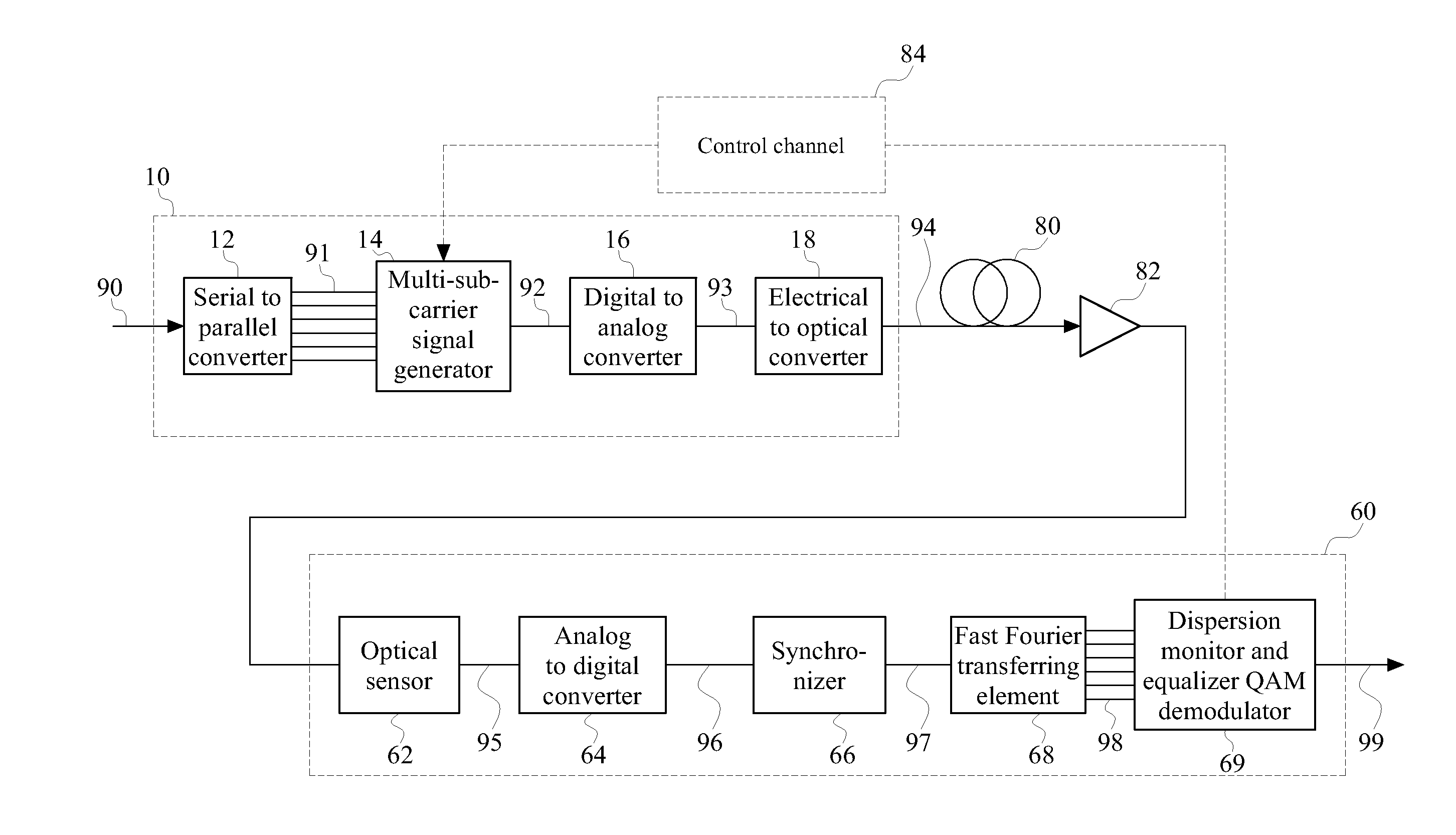
[0035]First, FIG. 3 is a schematic view of system architecture of a transmitter 10 and a receiver 60 of an optical orthogonal multiplexing system according to an embodiment of the present invention. As can be seen in the figure, the transmitter 10 converts a digital sequence signal 90 into an optical signal 94 and transmits the optical signal 94. This optical signal 94 is transmitted by an optical fiber 80 and amplified by an optical amplifier 82, and then received by the receiver 60.

[0036]The optical signal 94 is an orthogonal frequency-division multiplexing (OFDM) optical signal 94. The optical amplifier 82 may be, but not limited to, erbium-doped optical fiber amplifier. The optical 80 fiber is, but not limited to, a single mode fiber.

[0037]After receiving the optical signal 94, the receiver 60 estimates a total delay time of a group delay generated by the chromatic dispersion of the optical signal 94, and then returns the total delay time to the transmitter 10. The total delay t...


PUM


Abstract

A pre-compensation method for delays caused by optical fiber chromatic dispersion, a multi-sub-carrier signal generator applying the method, and a transmitter applying the signal generator are applicable to an optical orthogonal frequency-division multiplexing (OFDM) system. The pre-compensation method includes receiving a plurality of pre-compensation values, in which the pre-compensation values correspond to sub-carriers; and transmitting the sub-carriers after delaying the sub-carriers by time of the corresponding pre-compensation values. The delay time between the sub-carriers is estimated at a receiver end and a pre-compensation value of the transmitter is set according to the delay time. The transmitter delays the pre-compensation values respectively when transmitting the respective sub-carriers. Therefore, the respective sub-carriers are able to reach a receiver at nearly the same time, thereby achieving a purpose of pre-compensating for the delays caused by optical fiber chromatic dispersion.

Description

CROSS-REFERENCE TO RELATED APPLICATIONS[0001]This non-provisional application claims priority under 35 U.S.C. §119(a) on Patent Application No(s). 098115056 filed in Taiwan, R.O.C. on May 6, 2009 the entire contents of which are hereby incorporated by reference.BACKGROUND OF THE INVENTION[0002]1. Field[0003]The present invention relates to a transmitter capable of pre-compensating for delays caused by optical fiber chromatic dispersion in a system utilizing an optical orthogonal frequency-division multiplexing (OFDM) technology.[0004]2. Related Art[0005]An orthogonal frequency-division multiplexing (OFDM) system is an FDM system utilizing a digital multi-carrier modulation method. A plurality of orthogonal sub-carriers (also referred to as sub-bands) is used to transmit data. The data is cut into several parallel data streams (or referred to as channels) corresponding to the respective sub-carriers. For each sub-carrier, data transmission is performed with an orthogonal modulation t...

Claims


Application Information

Patent Timeline
IPC IPC(8): H04J14/02
CPCH04B10/2513H04L25/03343H04B10/548H04L2025/03414H04L2025/03802H04L27/2605
Inventor LIN, YU MIN
Owner IND TECH RES INST
Why Eureka
Try Eureka