
Near field coupling devices and associated systems and methods

Active Publication Date: 2010-11-11
ZEBRA TECH CORP
View PDF20 Cites 15 Cited by
  • Summary
  • Abstract
  • Description
  • Claims
  • Application Information

AI Technical Summary

Benefits of technology

[0014]In another embodiment, an apparatus comprising a processor is provided. The processor may be configured to receive indications of a transponder type and a transponder position justification; and connect one or more coupling elements of a near-field coupling device depending on at least the transponder type and the transponder position justification to configure a total characteristic impedance of the coupling elements relative to a terminating load of the near-field coupling device.
[0015]The processor configured to connect the one or more coupling elements may further include being configured to connect the one or more coupling elements to configure the total characteristic impedance of the coupling elements to be greater than or less than the terminating load. For example, the processor configured to connect the one or more coupling elements may include being configured to connect the one or more coupling elements to configure the total characteristic impedance of the coupling elements to be greater than the

Problems solved by technology

However, in some instances, errors in the encoding process (e.g., improperly encoded transponders or encoding failures) can occur due to the variations of the justification and type of transponders to be encoded.
The encoding errors largely arise from non-uniform location or orientation of the transponder on the media received by a printer-encoder.
As a result, the location of the transponders relative to the antenna of the printer-encoder may be unpredictable, and the electromagnetic field generated by the antenna of the printer-encoder may not be effective for encoding of the transponders.

Method used


Image

  • Near field coupling devices and associated systems and methods
  • Near field coupling devices and associated systems and methods
  • Near field coupling devices and associated systems and methods

Examples


Embodiment Construction

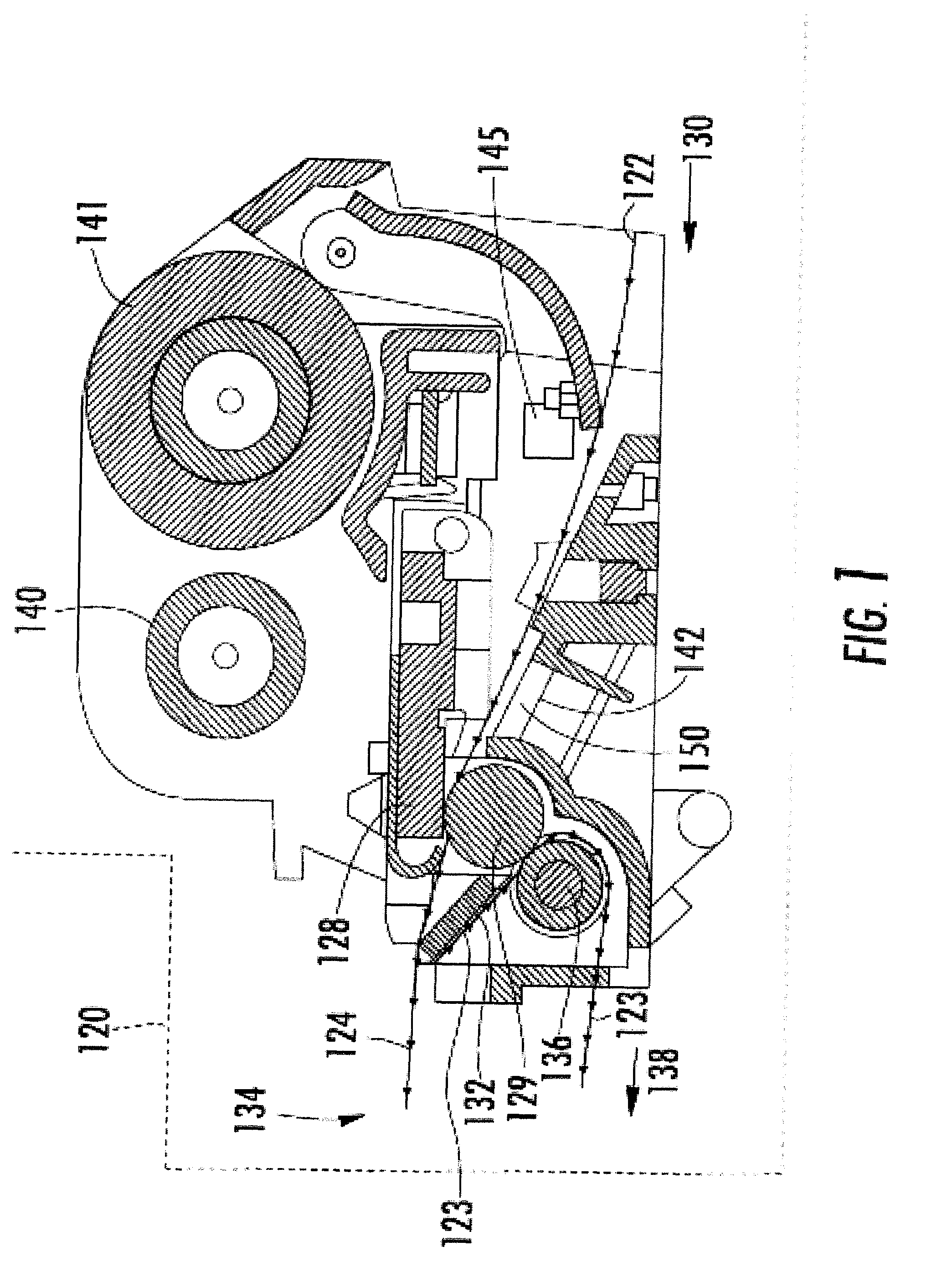
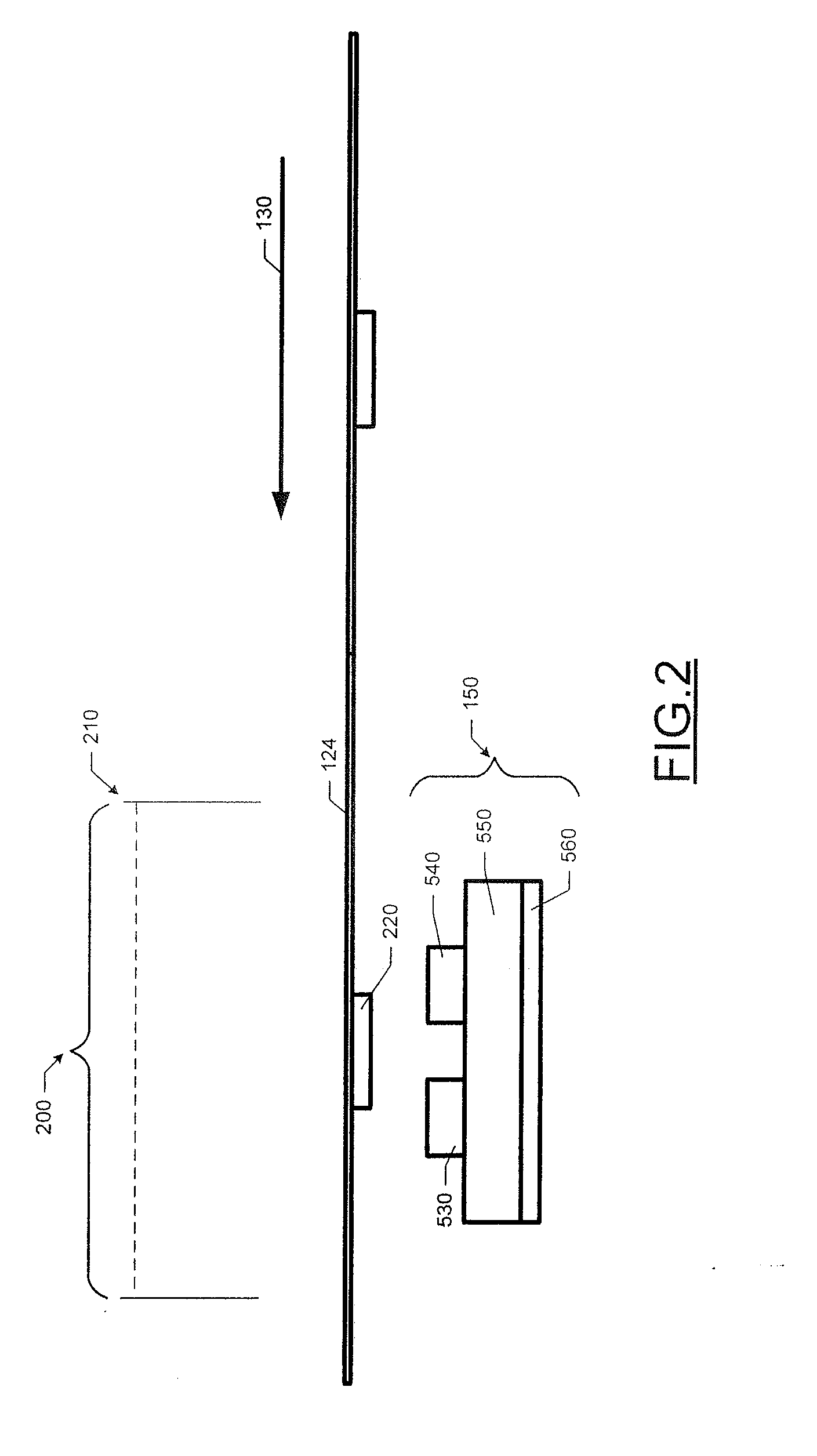
[0047]The present invention now will be described more fully hereinafter with reference to the accompanying drawings, in which some, but not all embodiments of the invention are shown. Indeed, this invention may be embodied in many different forms and should not be construed as limited to the embodiments set forth herein; rather, these embodiments are provided so that this disclosure will satisfy applicable legal requirements. Like numbers refer to like elements throughout. The term “exemplary,” as used herein, is not provided to convey any qualitative assessment, but is used instead to merely convey an illustration of an example.

[0048]Exemplary embodiments of the present invention concern an apparatus for enabling an RFID transceiver to communicate with a transponder that may be commingled among or positioned in close proximity to multiple adjacent transponders. As will be apparent to one of ordinary skill in the art, various exemplary embodiments of the present invention are descr...


PUM


Abstract

A near-field coupling device that may facilitate communications with a transponder is provided. The near-field coupling device may include a ground plane, a dielectric substrate, one or more conductive strips and a terminating load. The conductive strips together with the ground planes form coupling elements. The near-field coupling device further includes one or more switching elements for selectively connecting and disconnecting the coupling elements with a transceiver. The connected coupling elements define a total characteristic impedance. Using the switching element, the ratio between the total characteristic impedance of the connected coupling elements and the terminating load may be changed in order to adjust the distribution of an electromagnetic field along the coupling elements according to the type and position of the transponder to be processed.

Description

BACKGROUND[0001]1. Field of the Invention[0002]The present invention relates to RFID (Radio Frequency Identification) systems and, in particular, to near field antennas for such systems configured to selectively communicate with a targeted RFID transponder from among a group of adjacent transponders.[0003]2. Description of Related Art[0004]RFID technology is rapidly becoming essential to not only accurately manage assets and inventory, but also in a variety of other practical applications. With respect to inventory applications, RFID tags, also known as transponders, are being used to count and identify inventory in retail stores, warehouses, shipping containers, and the like, to allow for more accurate bookkeeping and ordering of replacement or replenishment goods. Moreover, it has been determined that many other applications for RFID technologies are becoming increasingly beneficial and / or economical. For example, RFID transponders are being used in security applications to grant ...

Claims


Application Information

Patent Timeline
IPC IPC(8): H04B5/00
CPCG06K7/10297H04B5/0062G06K17/0009H04B5/02B41J3/407H01Q3/24G06K17/0025H04B5/0068H04B5/45H04B5/77H04B5/48
Inventor TSIRLINE, BORIS Y.TIAN, MAOTORCHALSKI, KARL
Owner ZEBRA TECH CORP
Learn More