Endoscope with distal tip having encased optical components and display orientation capabilities

a technology of endoscope and optical components, which is applied in the field of endoscope devices, can solve the problems of reducing the quality of images collected during an endoscopic procedure, the lens may not be precisely positioned on the optical fiber, and the optical components can become loose or detached from the endoscope during use,

Active Publication Date: 2010-11-11
BOSTON SCI SCIMED INC
View PDF4 Cites 160 Cited by
  • Summary
  • Abstract
  • Description
  • Claims
  • Application Information

AI Technical Summary

Benefits of technology

[0015]Various embodiments of the disclosure may include one or more of the following aspects: the actuator may be a first actuator and the method may further include actuating a second actuator to send a signal to the image display device such that a mark may be displayed within the displayed image of the body lumen at an area of interest; and the actuating may include rotating the actuator relative to the handle of the endoscope such that a reference mark on the actuator may be at a desired rotational location relative to the handle and the rotational location of the reference mark may be associated with an orientation of the displayed image relative to the endoscope.

Problems solved by technology

In such a case, the lens may not be precisely positioned on the optical fiber because the glue adhering the lens to the endoscope may not have been uniformly applied, or the lens may have moved relative to the position of the optical fiber before the glue has completely dried.
In addition, optical components can become loose or detached from the endoscope during use.
This can result in reduced quality of images gathered during an endoscopic procedure and / or components can become detached from the endoscope and disposed within the patient's body.
The sterilization procedure can be expensive and subject the delicate endoscope components (e.g., lenses) to a harsh environment that may crack or otherwise damage the endoscope components, rendering the endoscope inoperable.
The diffuser is typically formed with a different material than the endoscope tip, This, together with the small size required of the diffuser, can make such a diffuser difficult to manufacture.
In some known endoscope systems, it can be difficult for the practitioner to discern the orientation of an image as he or she navigates the endoscope tip through a body lumen.
If the practitioner misinterprets the orientation of the image, it can be difficult for the practitioner to relocate an area of interest during a subsequent procedure.

Method used


Image

  • Endoscope with distal tip having encased optical components and display orientation capabilities
  • Endoscope with distal tip having encased optical components and display orientation capabilities
  • Endoscope with distal tip having encased optical components and display orientation capabilities

Examples


Embodiment Construction

[0026]Reference will now be made in detail to the present embodiments (exemplary embodiments) of the invention, examples of which are illustrated in the accompanying drawings. Wherever possible, the same reference numbers will be used throughout the drawings to refer to the same or like parts.

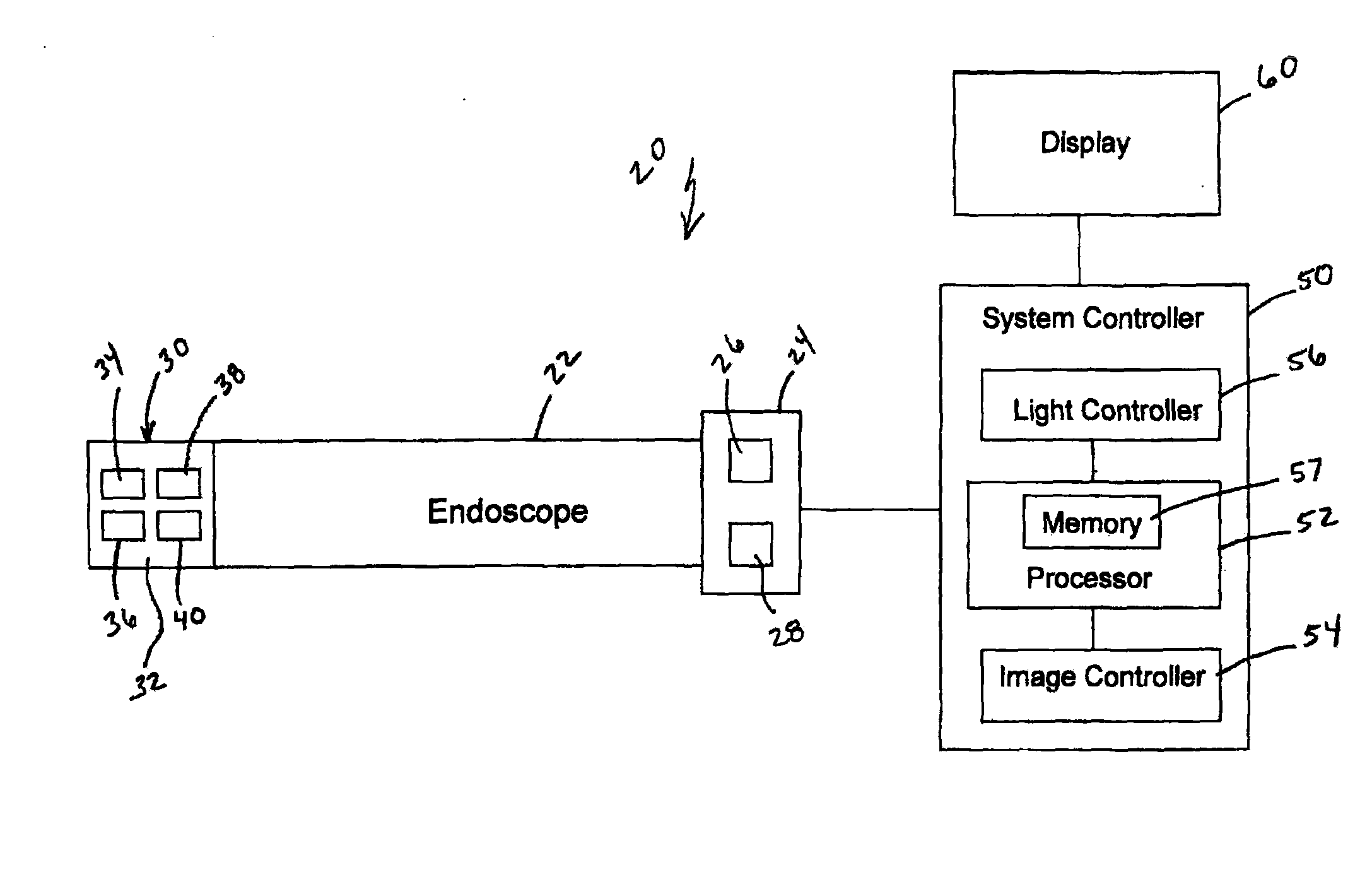
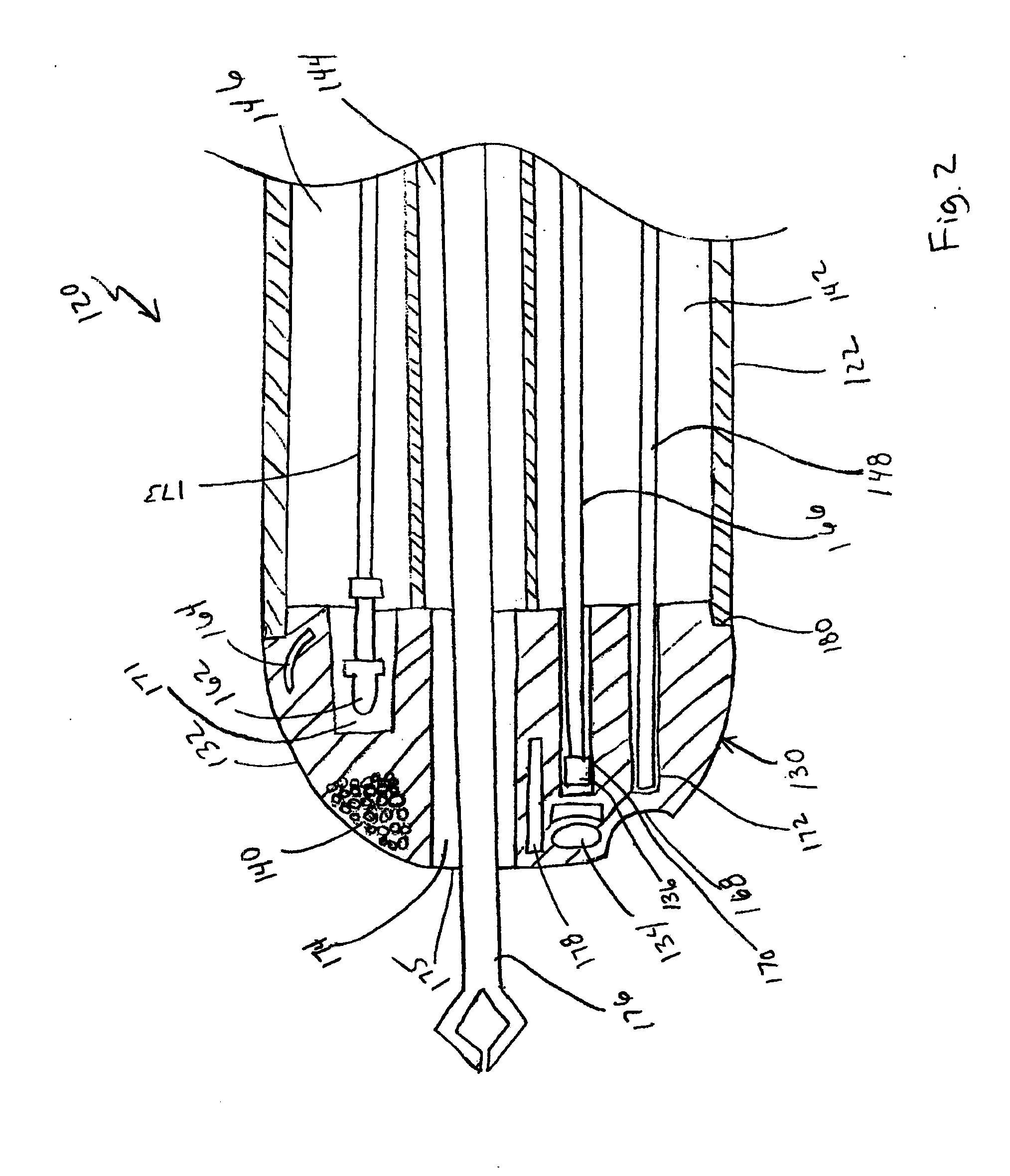
[0027]Endoscopes and methods of using endoscopes are described herein. In one embodiment, an endoscope includes an endoscope tip having a unitary housing that encases various optical components. For example, such optical components can include image detectors, light sources, fiberoptics, light shields, lenses, etc. The housing can be formed with a transparent material that can be processed to induce micro-defects within the housing. Such micro-defects can provide light diffusing capabilities. The micro-defects can be formed with a variety of different patterns to shape an illumination beam of light from a light source (e.g., a fiberoptic or LED light source). In some embodiments, an endoscope s...


PUM


Abstract

An apparatus according to one embodiment includes an endoscope tip including a housing that is monolithically formed of a transparent material. At least one optical component is at least partially encased within the housing. The optical component can be, for example, a light source, a fiber optic, an imaging sensor, a lens, a reflector or a light shield. In another embodiment, an apparatus includes an endoscope having a distal end portion that includes a housing. The housing is monolithically formed with a transparent material and a light source is at least partially encased within the housing. The housing also includes a micro-defects portion within the transparent material of the housing. The micro-defects portion is configured to provide a selected output shape of a beam of light produced by the light source.

Description

CROSS REFERENCE TO RELATED APPLICATION[0001]This patent application claims the benefit of priority under 35 U.S.C. §119 to U.S. Provisional Patent Application No. 61 / 176,624, filed May 8, 2009, which is herein incorporated by reference in its entirety.FIELD OF THE INVENTION[0002]The invention relates generally to medical devices and more particularly to endoscope devices and methods for using such devicesBACKGROUND OF THE INVENTION[0003]A variety of different types of endoscopes can be used in various medical, dental, and veterinary applications. Some known endoscopes include optical components such as a light source, an image sensor and / or lenses, at a distal end of the endoscope. It is often desirable to provide light focusing capabilities within the endoscope through the use, for example, of lenses or other optical components coupled to the endoscope distally, near a light source (e.g., fiber optic or LED), or near an image sensor (e.g., CCD). Such components are typically couple...

Claims


Application Information

Patent Timeline
Patent Type & Authority Applications(United States)
IPC IPC(8): A61B1/06A61B1/00A61B1/04
CPCA61B1/00096A61B1/018A61B1/05A61B1/0669A61B1/0684A61B1/00188A61B1/0676
Inventor ROBERTSON, DAVID W.
Owner BOSTON SCI SCIMED INC
Why Eureka
Try Eureka