Expandable support device and method of use

a support device and expandable technology, applied in the direction of osteosynthesis devices, prosthesis, spinal implants, etc., can solve the problems of radial expansion of the expandable support device, and achieve the effect of improving bone structur

Active Publication Date: 2010-11-18
NUVASIVE
View PDF32 Cites 396 Cited by
  • Summary
  • Abstract
  • Description
  • Claims
  • Application Information

AI Technical Summary

Problems solved by technology

The longitudinal compression can result in radial expansion of the expandable support device.

Method used


Image

  • Expandable support device and method of use
  • Expandable support device and method of use
  • Expandable support device and method of use

Examples


Embodiment Construction

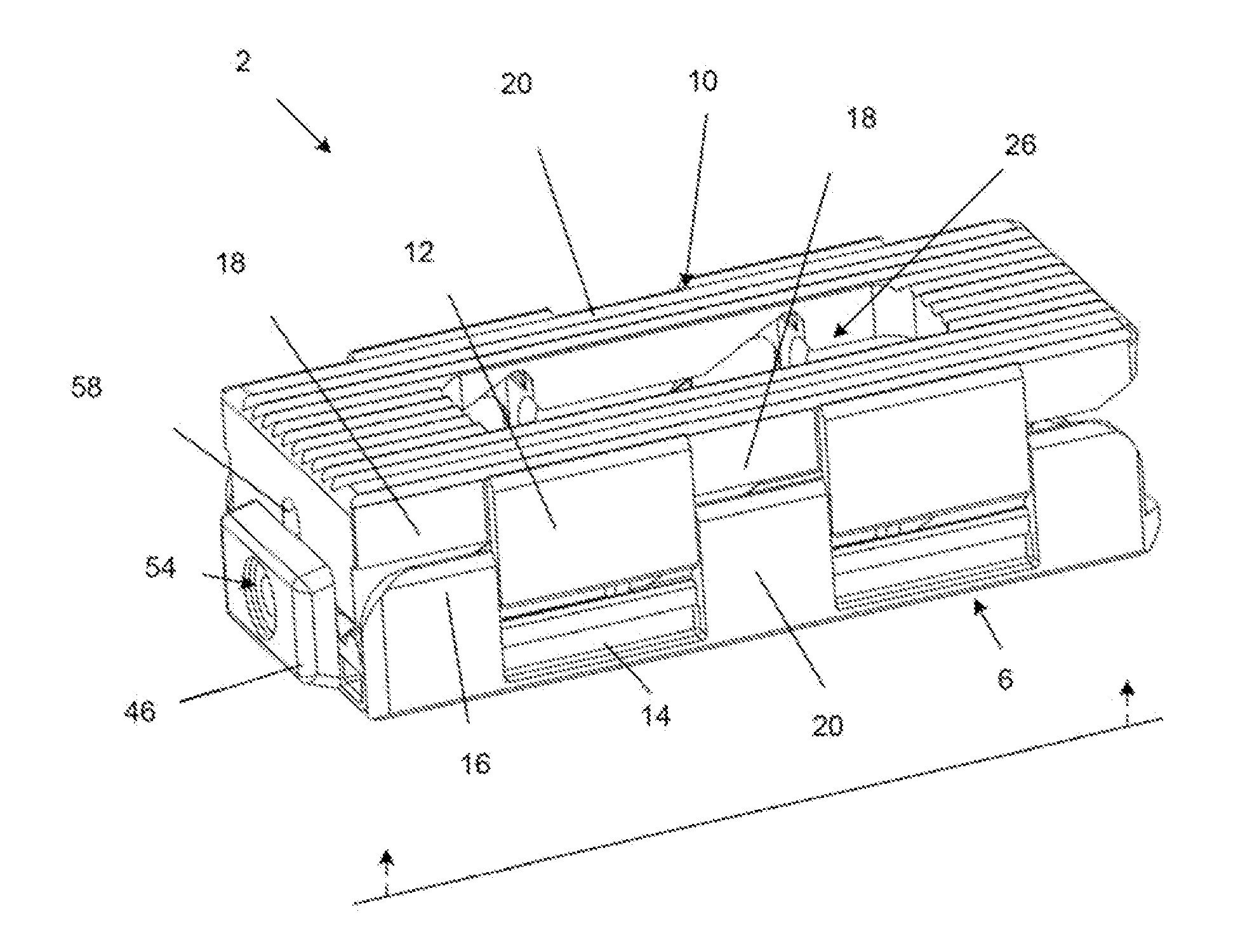
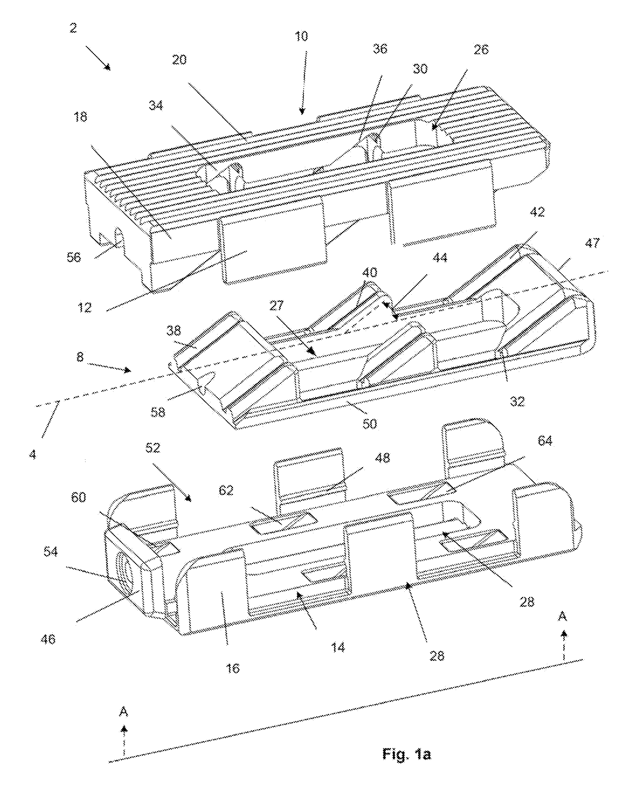
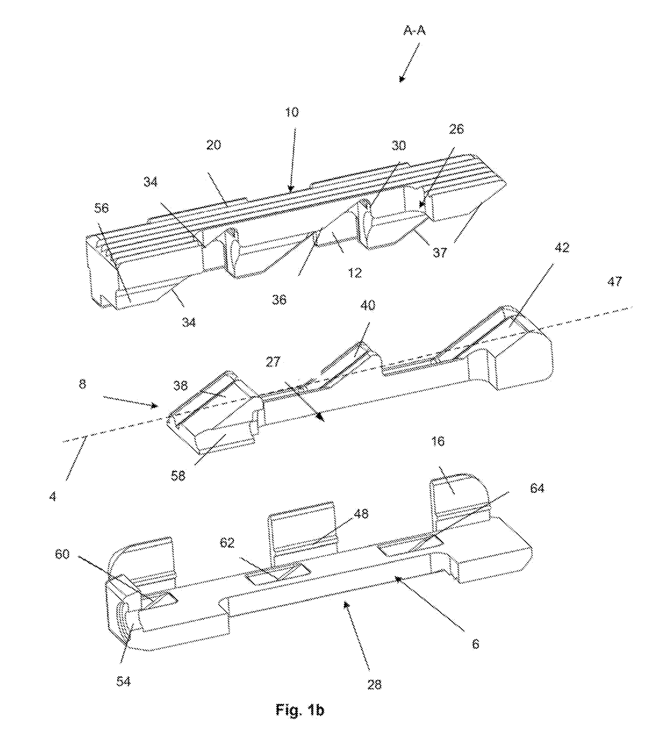
[0048]FIGS. 1a and 1b illustrate an exploded view of an expandable support device 2 that can be implanted in a bone, such as a compression fracture in a vertebra, in the intervertebral space between two vertebrae, or in soft tissue, such as a herniated intervertebral disc. The expandable support device 2 can be biocompatible. The expandable support device 2 can be used, for example, for methods of repairing vertebral bone fractures or supporting adjacent vertebral bodies for fusion. The expandable support device 2 can have a first longitudinal end and a second longitudinal end along a longitudinal axis 4.

[0049]The expandable support device 2 can have a base or bottom 6 (base and bottom are used interchangeably), a middle 8, and a top 10. The base or bottom 6 and top 10 can be or have plates, panels, struts (e.g., legs), ports, cells, and combinations thereof. The base 6 and top 10 can be configured to be slidably attachable to the middle 8. Either the top 10, the base 6, or neither,...


PUM

PropertyMeasurementUnit
diameteraaaaaaaaaa
diameteraaaaaaaaaa
ramp angleaaaaaaaaaa

Abstract

An expandable support device for tissue repair is disclosed. The device can be used to repair hard or soft tissue, such as bone or vertebral discs. A method of repairing tissue is also disclosed. The device and method can be used to treat compression fractures. The compression fractures can be in the spine. The device can be deployed by compressing the device longitudinally resulting in radial expansion.

Description

CROSS-REFERENCE TO RELATED APPLICATIONS[0001]This application claims the benefit of U.S. Provisional Application No. 61 / 178,355, filed 14 May 2009, which is herein incorporated by reference in its entirety.BACKGROUND OF THE INVENTION[0002]1. Field of the Invention[0003]This invention relates to devices for providing support for biological tissue, for example to fuse vertebral bodies, repair herniated discs, and / or repair spinal compression fractures, and methods of using the same.[0004]2. Description of Related Art[0005]Some conditions of the spine result from degradation or injury to the bone structures of the spine, typically the vertebral body. These can be the result of bone degeneration such as through osteoporosis or trauma, such as compression fractures. breakdown or injury to the boney structures in the spine can result in pain and spinal deformity with comorbidities.[0006]Vertebroplasty is an image-guided, minimally invasive, nonsurgical therapy used to strengthen a broken ...

Claims


Application Information

Patent Timeline
Patent Type & Authority Applications(United States)
IPC IPC(8): A61F2/44
CPCA61B17/8858A61F2310/00976A61F2/4611A61F2002/2817A61F2002/2835A61F2002/3008A61F2002/30082A61F2002/3037A61F2002/30372A61F2002/30383A61F2002/30403A61F2002/30507A61F2002/30518A61F2002/3052A61F2002/30556A61F2002/30579A61F2002/30736A61F2002/30828A61F2002/30904A61F2002/4475A61F2210/0095A61F2220/0025A61F2220/0033A61F2250/0009A61F2250/0098A61F2310/00017A61F2310/00023A61F2310/00029A61F2310/00071A61F2310/00083A61F2310/00101A61F2310/00131A61F2310/00137A61F2310/00155A61F2310/00353A61F2310/00365A61F2/447A61F2002/30593
Inventor GREENHALGH, E. SKOTTROMANO, JOHN-PAUL
Owner NUVASIVE
Why Eureka
Try Eureka