
Control apparatus for vehicle drive system

a control apparatus and vehicle technology, applied in the direction of engine-driven generators, machine/engine control, process and machine control, etc., can solve the problems of engine stopping, engine rotation speed falling, pinion gear burning out,

Active Publication Date: 2010-11-18
DENSO CORP +1
View PDF18 Cites 26 Cited by
  • Summary
  • Abstract
  • Description
  • Claims
  • Application Information

AI Technical Summary

Benefits of technology

[0008]It is therefore an object of the present invention to provide a control apparatus for a vehicle drive system, which can restrict a secondary failure, which is a failure of a planetary gear set, from occurring in case of a change in a vehicle operation mode to a limp-home travel mode.

Problems solved by technology

However, if the operation of the engine is stopped immediately at the time of changing the vehicle operation mode to the limp-home travel mode in response to occurrence of abnormality in the engine system or the first MG system while traveling at high speeds, the engine rotation speed falls and the engine stops while the travel speed of the vehicle is still relatively high.
If the pinion gear rotation speed exceeds the allowable maximum limit value, the pinion gear will be burned out and the planetary gear set will fail and become inoperative.
This will result in a secondary failure.
As a result, repair cost will greatly increase.
If the pinion gear rotation speed exceeds the allowable maximum limit value and the planetary gear set fails causing the secondary failure when the vehicle operation mode is changed to the limp-home travel mode due to abnormality in the inverter of the first MG in the first MG system, not only the inverter of the first MG system, which is the original cause for the abnormality, but also the transfer assembly unit (the first MG, the planetary gear set and the like) need be replaced with new ones in a repair work.
As a result, repair cost will greatly increase.

Method used


Image

  • Control apparatus for vehicle drive system
  • Control apparatus for vehicle drive system
  • Control apparatus for vehicle drive system

Examples


first embodiment

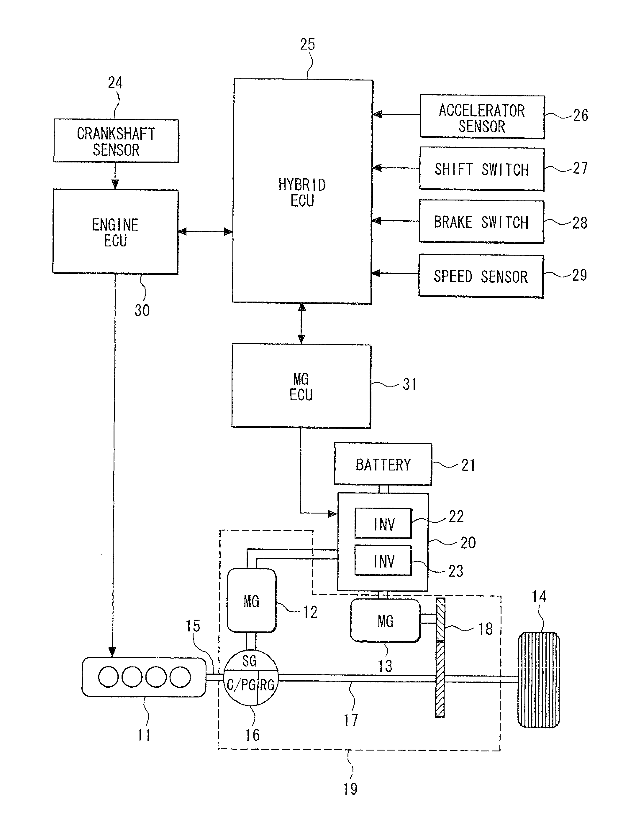
[0024]The first embodiment is shown in FIGS. 1 to 8A and 8B.

[0025]Referring first to FIG. 1, in which an entire drive system of a hybrid vehicle is shown, an internal combustion engine 11, a first motor generator (MG) 12 and a second motor generator (MG) 13 are mounted in a hybrid vehicle. The engine 11 and the second MG 13 are used as a drive power source for driving wheels 14. The drive power of a crankshaft 15 of the engine 11 is distributed to two systems by a planetary gear set 16, which is a drive power distribution mechanism.

[0026]The planetary gear set 16 includes a sun gear SG, a pinion gear PG and a ring gear RG. The crankshaft 15 of the engine 11 is coupled to the pinion gear PG via a planet carrier C. A rotation shaft of the first MG 12, which is primarily used as an electric power generator 12, is coupled to the sun gear SG.

[0027]A propeller shaft (drive shaft) 17 is coupled to the ring gear RG. The drive power of the propeller shaft 17 is transferred to the wheels 14 v...

second embodiment

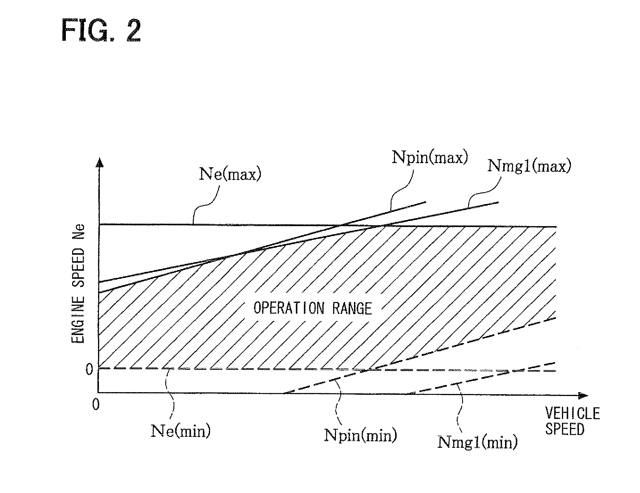
[0066]The second embodiment of the present invention will be described in detail with reference to FIGS. 9 to 11. The description is limited to parts different from the first embodiment, while being omitted or simplified with respect to substantially the same parts as in the first embodiment. According to the second embodiment, based on that the rotation speed of the ring gear RG coupled to the wheel 14 side can be lowered by lowering the vehicle travel speed, the hybrid ECU 25 is configured to execute control routines shown in FIGS. 9 and 10. Specifically, when the vehicle operation mode is changed to the limp-home travel mode due to abnormality in the first inverter 22, over rotation limitation control is performed to lower the vehicle travel speed so that the pinion gear rotation speed does not exceed the limit value. Thus, even if the engine rotation speed falls, the difference between the rotation speeds of the ring gear RG coupled to the wheel 14 side and the carrier C coupled...


PUM


Abstract

Over rotation limitation control is performed to control an engine rotation speed so that a rotation speed of a pinion gear of a planetary gear set will not exceed a limit value, when a travel mode is changed to a limp-home travel mode in response to an abnormality in an inverter for a first motor generator. With this over rotation limitation control, a difference between rotation speeds of a ring gear coupled to a wheel side and a carrier coupled to an engine side. Thus, when the limp-home travel mode is performed due to the abnormality in the inverter for the first motor generator, a secondary failure, in which the pinion gear burns out and the planetary gear set fails, is prevented.

Description

CROSS REFERENCE TO RELATED APPLICATION[0001]This application is based on and incorporates herein by reference Japanese Patent Application No. 2009-117254 filed on May 14, 2009.FIELD OF THE INVENTION[0002]The present invention relates to a control apparatus for a vehicle drive system, in which an internal combustion engine, a first motor generator and a wheel drive shaft are coupled through a planetary gear set and a second motor generator is coupled to the wheel drive shaft.BACKGROUND OF THE INVENTION[0003]Hybrid vehicles are demanded more and more recently from the standpoint of social demands such as low fuel consumption and low exhaust emission. In hybrid vehicles, which are presently available in the market, as disclosed in JP 2001-329884A, an internal combustion engine, a first motor generator (MG) used primarily as a generator and a second motor generator (MG) used primarily to drive wheels are provided. The crankshaft of the internal combustion engine is coupled to a planet c...

Claims


Application Information

Patent Timeline
IPC IPC(8): G06F19/00B60K6/445B60L15/20B60L50/16B60T7/12B60W10/06B60W10/10B60W10/18B60W20/00F02D29/02F16H59/38F16H59/46F16H59/54F16H61/02F16H63/50
CPCB60K1/02B60K6/365B60W20/50Y02T10/6239Y02T10/7258B60K6/445Y02T10/62Y02T10/72
Inventor TAKAHASHI, SHIGENORI
Owner DENSO CORP
Features
  • Generate Ideas
  • Intellectual Property
  • Life Sciences
  • Materials
  • Tech Scout
  • Unparalleled Data Quality
  • Higher Quality Content
  • 60% Fewer Hallucinations
Learn More