
Pressure sensor

a pressure sensor and sensor technology, applied in the field of pressure sensors, can solve the problems of reducing measurement precision, significant time period, and insufficient measurement accuracy of pressure sensors

Inactive Publication Date: 2010-11-25
TOYOTA JIDOSHA KK
View PDF7 Cites 4 Cited by
  • Summary
  • Abstract
  • Description
  • Claims
  • Application Information

AI Technical Summary

Benefits of technology

The present invention provides a pressure sensor that can quickly defrost surface water in the pressure-detecting section, even at low temperatures, and prevent abnormal deformation of the pressure-detecting section due to tightening of the screw during mounting of the pressure sensor. The pressure sensor includes an engagement section, a pressure-detecting section, a displacement sensor, and a buffer section that absorbs abnormal displacement occurring in the pressure-detecting section. The buffer section has a cylindrical internal buffer section and a cylindrical external buffer section connected at one end to the pressure-detecting section and at the other end to the engagement section, and a end bottom plate. The internal and external buffer sections have circular cylindrical shapes, and the end bottom plate has an annular shape.

Problems solved by technology

In the pressure sensor of related art, because the connecting chamber is provided and the pressure-detecting section does not face the reaction gas flow path, when the moisture which is present on the pressure-receiving surface of the pressure-detecting section facing the side of the connecting chamber freezes, even if a reaction gas at a temperature exceeding 0° C. flows, the temperature in the connecting chamber is not increased, and, there is a problem in that a significant time period is required until the moisture is defrosted.
Because of this, measurement by the pressure sensor is not assured until the moisture is defrosted and the pressure sensor is recovered.
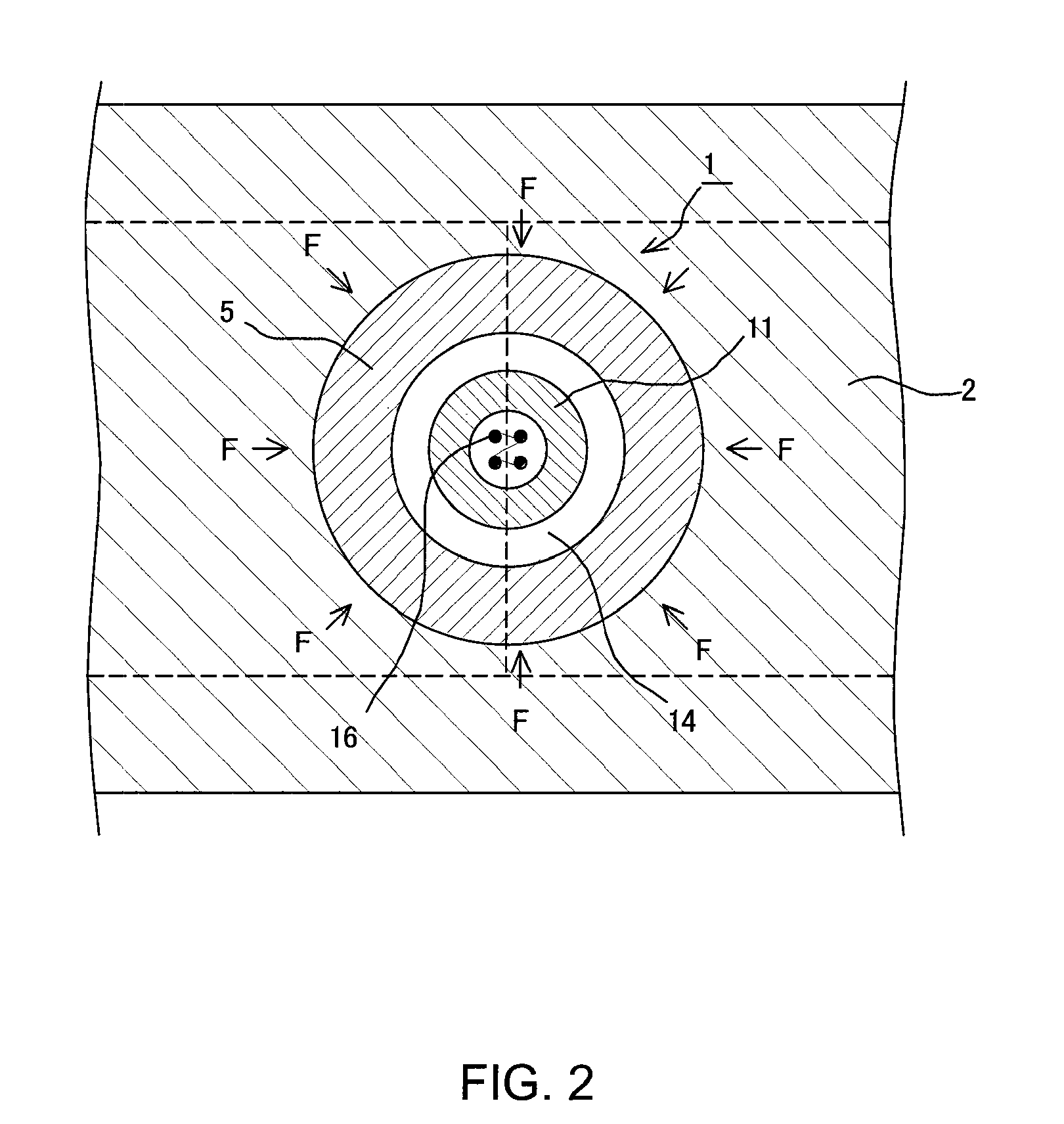
Because of this stress, there is a problem in that an abnormal deformation occurs in the pressure-detecting section and the measurement precision is reduced.

Method used


Image

  • Pressure sensor
  • Pressure sensor
  • Pressure sensor

Examples


Embodiment Construction

[0021]A preferred embodiment of the present invention will now be described in detail with reference to the drawings.

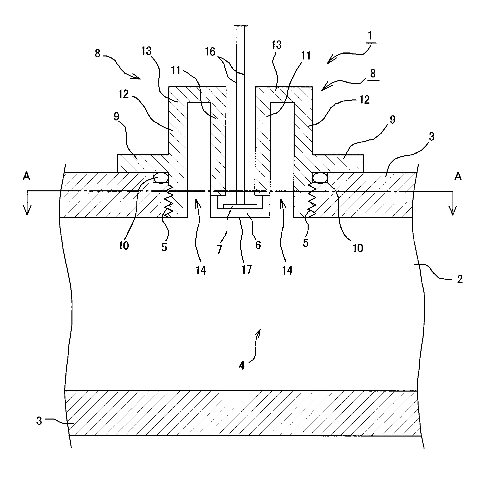
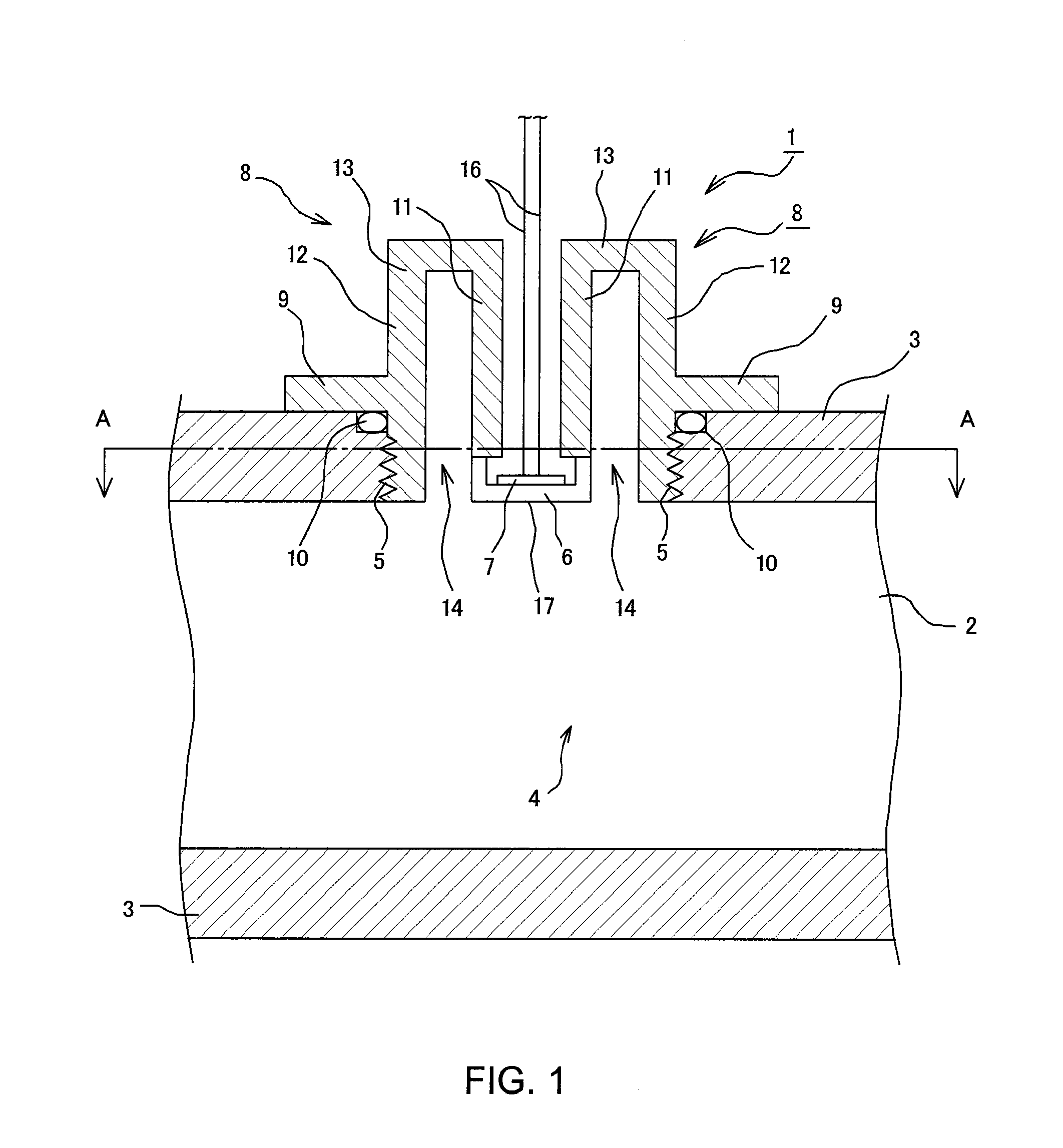
[0022]FIG. 1 shows a schematic structure of a preferred embodiment of a pressure sensor. A pressure sensor 1 comprises an engagement section 5, a diaphragm 6 which serves as a pressure-detecting section, a displacement sensor 7, and a buffer section 8.

[0023]The engagement section 5 is threaded and engages a screw section provided on a pipe wall 3 of a reaction gas pipe 2. With the engagement section 5, the screw is tightened and the pressure sensor 1 is fixed to the reaction gas pipe 2. In addition, a seal member 10 is provided on the engagement section 5 and seals the structure, so that the reaction gas or the like does not leak from the reaction gas pipe 2. Moreover, the pressure sensor 1 comprises a flange 9 at its outer periphery. With this flange 9, the tightening position of the engagement section 5 is determined. The flange 9 also presses the seal member 10 dur...


PUM

PropertyMeasurementUnit
temperatureaaaaaaaaaa
pressureaaaaaaaaaa
displacementaaaaaaaaaa

Abstract

A pressure sensor is arranged on a supply / discharge pipe of a reactive gas to be supplied to or discharged from a fuel cell, and measures the pressure of the reactive gas in the pipe. The pressure sensor is provided with an engaging section which has a screw and engages with a pipe wall of the pipe; a pressure detecting section, which faces a reactive gas channel of the pipe and detects the pressure inside the pipe by displacement; a displacement sensor, which is arranged in the pressure detecting sensor and measures displacement of the pressure detecting section; and a buffer section, which connects the engaging section with the pressure detecting section by sandwiching a buffer layer which communicates with the reactive gas channel of the pipe, and eliminates abnormal displacement of the pressure detecting section by deforming to a stress generated by torque of the screw, at the time when the pressure sensor is engaged with the pipe.

Description

[0001]This is a 371 national phase application of PCT / JP2007 / 072054 filed 7 Nov. 2007, claiming priority to Japanese Patent Application No. JP 2006-312539 filed 20 Nov. 2006, the contents of which are incorporated herein by reference.FIELD OF THE INVENTION[0002]The present invention relates to a pressure sensor, and more particularly, to a pressure sensor which is provided on a supply and discharge pipe of a reaction gas supplied to or discharged from a fuel cell and which measures a pressure of the reaction gas in the pipe.BACKGROUND OF THE INVENTION[0003]A fuel cell generates power by supplying a fuel gas to a fuel pole (anode electrode) and an oxidizing gas to an oxidation agent pole (cathode electrode), thereby allowing an electrochemical reaction between the fuel gas and the oxidizing gas. In a fuel cell, a fuel gas supply pipe for supplying the fuel gas to the body of the fuel cell, a fuel gas discharge pipe for discharging the fuel gas from the fuel cell body, an oxidizing ga...

Claims


Application Information

Patent Timeline
Patent Type & Authority Applications(United States)
IPC IPC(8): G01L19/00
CPCG01L19/0023G01L19/146G01L23/24Y02E60/50H01M8/04298H01M8/0438H01M2008/1095H01M8/04089G01L19/00H01M8/04H01M8/10
Inventor YAMAGISHI, NORIO
Owner TOYOTA JIDOSHA KK
Learn More