

Waste bin
a technology for storing containers and waste, applied in the field of waste containers, can solve the problems of blockage, pollution of waterways, and leaching of toxic water from the setting slurry,
- Summary
- Abstract
- Description
- Claims
- Application Information
AI Technical Summary
Benefits of technology
Problems solved by technology
Method used
Image

Examples
first preferred embodiment
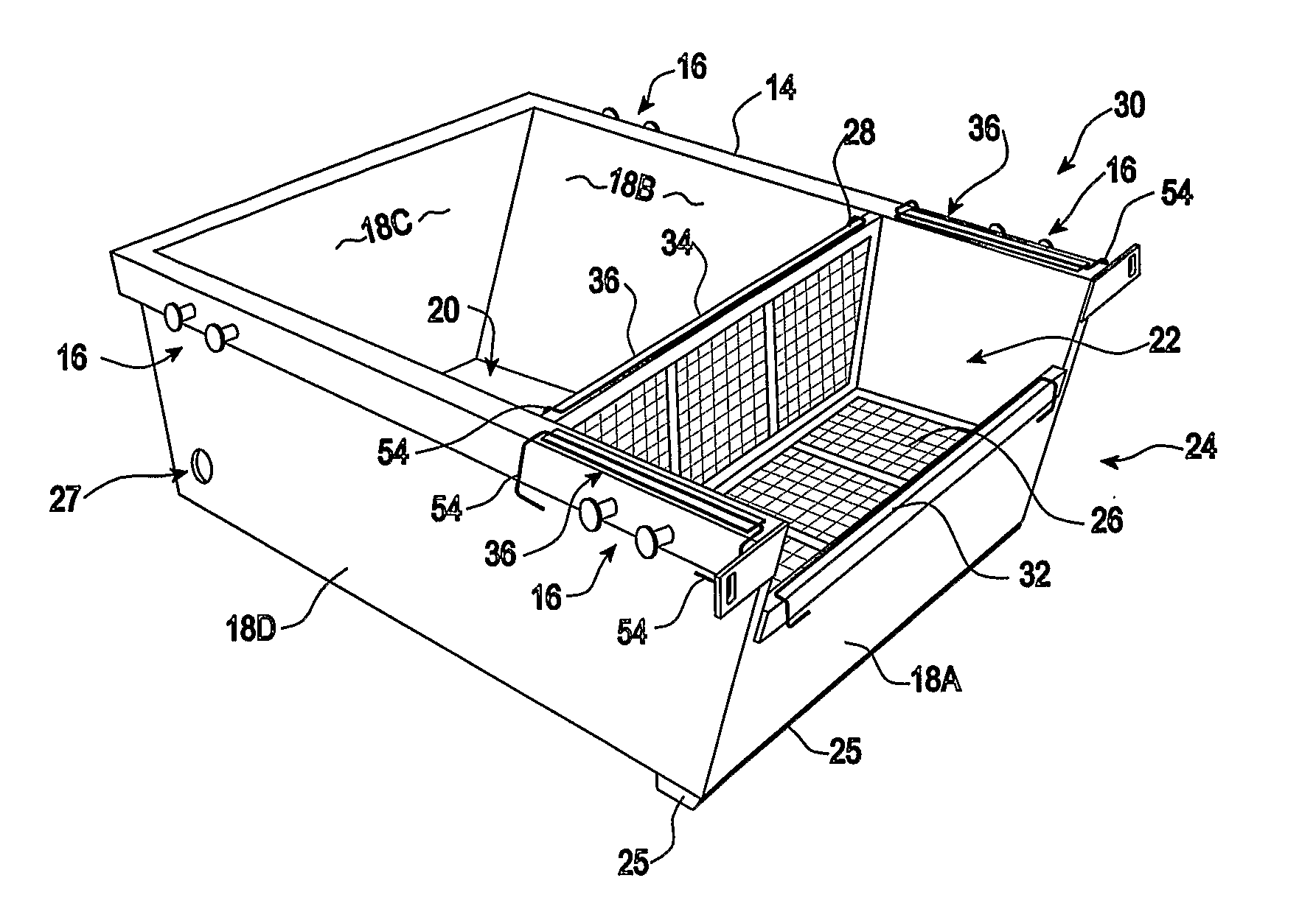
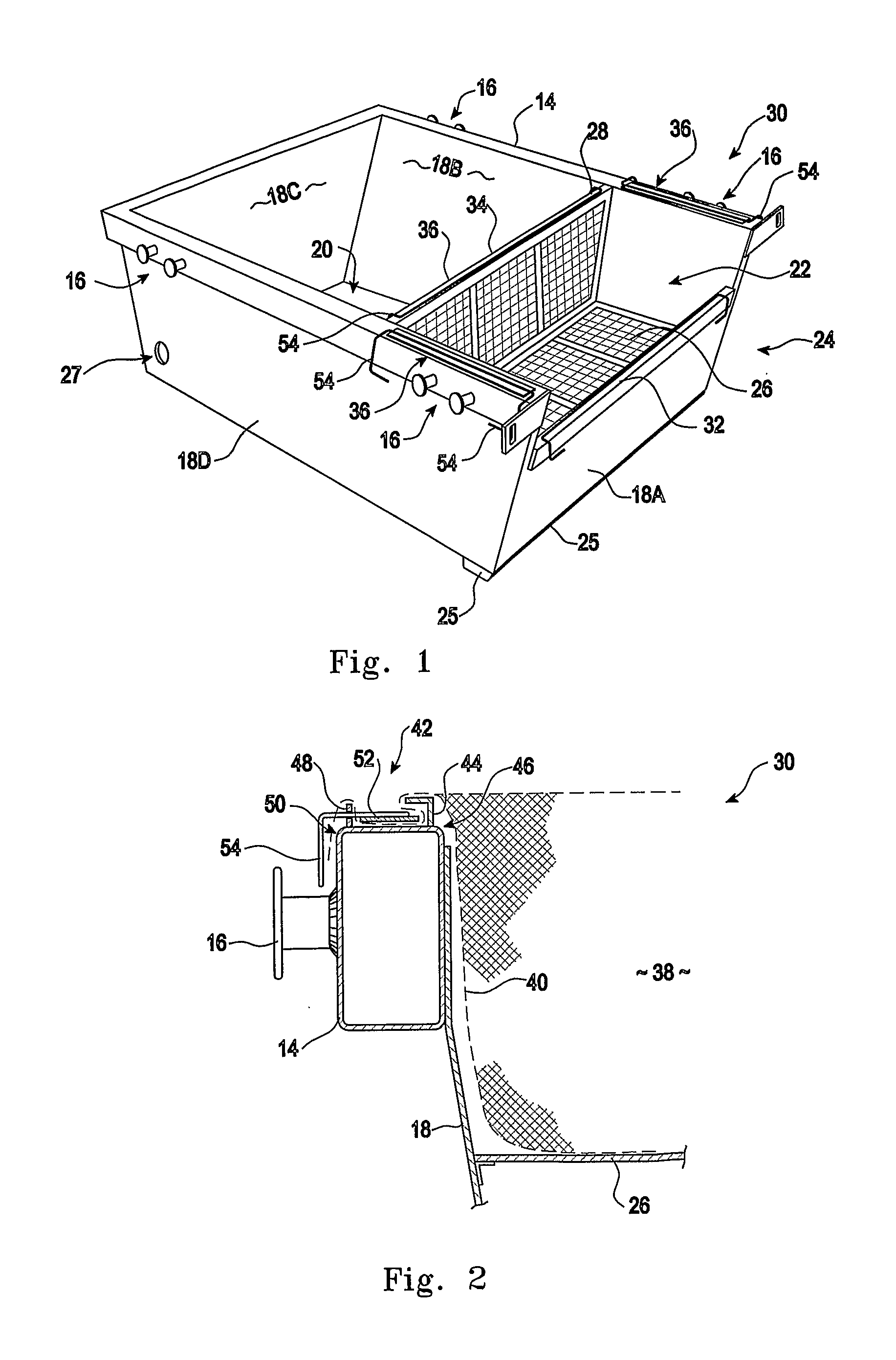
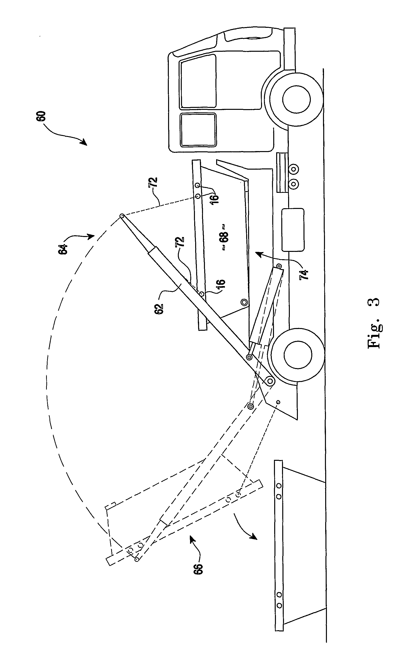
[0062]With reference to FIG. 1, a waste handling system 10 is comprised of a waste handling bin 12, sometimes known as a skip. Such bins are of welded steel construction having a reinforced upper rim 14 to which are attached at least four lifting fixtures 16 disposed along two opposing sides of the bin. The four sides 18A, 18B, 18C and 18D all slope inwardly from rim 14 to the base 20 so that bins may be nested together for economy of transport. Lifting fixtures 16 are arranged so as to allow attachment of lifting means (as can be seen in FIG. 3) for loading and unloading bins onto and off special transport vehicles. Alternatively, bins may be lifted by other means such as cranes for example.
[0063]The waste handling bin 12 is modified from a standard bin, by the provision of a filter element support rack 22. For the particular purpose of handling residual concrete waste, bin 12 may preferably be further modified by the provision of a cut out portion 24 in side 18A to allow for the l...
second preferred embodiment
[0069]In this preferred embodiment with reference to FIG. 9, a waste skip 210 may again be modified as described above, that is with a lowered side portion to allow ready access to the skip by a concrete truck discharge chute. The skip may again be fitted with a tilting support to direct liquid waste to one end of the bin for discharge via an outlet or pumping arrangement.
[0070]However in the present preferred embodiment with reference to FIG. 9, the removable filter element 238 is not retained at the perimeter 214 of the waste bin 210. Rather it is supported and releasably attached to separate filter support structure222 supported within the bin. An exemplary arrangement is shown in FIG. 9, in which a filter supporting basket structure 222 is located in the waste bin 210. In the example shown in FIG. 9, basket structure 222 is supported on a grating 226, itself supported on ledges or supporting structures 227 welded to the inside surfaces of the waste bin. It will be understood tha...
third preferred embodiment
[0087]In a third preferred embodiment of the invention, with reference to FIG. 10 a special waste bin 310 is provided for the specific purpose of receiving waste concrete slurry from a mobile concrete pumping unit 312. Typically a pumping unit is mounted on a heavy truck 314 and arranged with a receiving hopper 316 and concrete pump 318 at the rear of the vehicle, as shown in FIG. 10. Ready mixed concrete from a ready mixed concrete truck is fed into the hopper 316 with the pump 318 driving the concrete through conduits 320 to a location of use remote from the pumping unit 312.
[0088]The hopper 316 is located at a level adapted to allow feeding of concrete by the chute of a ready mixed concrete truck, as described above and as shown in FIG. 4, so that perforce the concrete pump 318, which is of course located below the hopper 316, is quite close to ground level. The special waste bin 310 of this embodiment, provides a waste handling system for the slurry deriving from the cleaning of...
PUM
| Property | Measurement | Unit |
|---|---|---|
| size | aaaaa | aaaaa |
| size | aaaaa | aaaaa |
| size | aaaaa | aaaaa |
Abstract
Description
Claims
Application Information