Optical element position adjusting mechanism and optical element position adjusting method, exposure apparatus using same, and device manufacturing method

Inactive Publication Date: 2010-11-25
CANON KK
View PDF1 Cites 0 Cited by
  • Summary
  • Abstract
  • Description
  • Claims
  • Application Information

AI Technical Summary

Benefits of technology

[0006]In consideration of the above-mentioned facts, the present invention provides a self-supporting optical element position adjusting mechanism that is capable of performing highly accurate positioning of an optical element without using a sensor and has high position stability, and an optical element position adjusting method, an exposure apparatus using the same; and a device manufacturing method.
[0008]According to the present invention, both highly accurate positioning using a flexure guide and position stability by adjusting the frictional force of a clamp may be achieved without using a sensor.

Problems solved by technology

However, the technique disclosed in Japanese Patent Laid-Open No. 2008-242448 requires a permanent inclusion of a sensor, and thus, the degree of freedom in disposing a sensor may be undesirably limited depending on the wiring of the sensor.
Furthermore, maintenance may become difficult due to wiring.

Method used


Image

  • Optical element position adjusting mechanism and optical element position adjusting method, exposure apparatus using same, and device manufacturing method
  • Optical element position adjusting mechanism and optical element position adjusting method, exposure apparatus using same, and device manufacturing method
  • Optical element position adjusting mechanism and optical element position adjusting method, exposure apparatus using same, and device manufacturing method

Examples


first embodiment

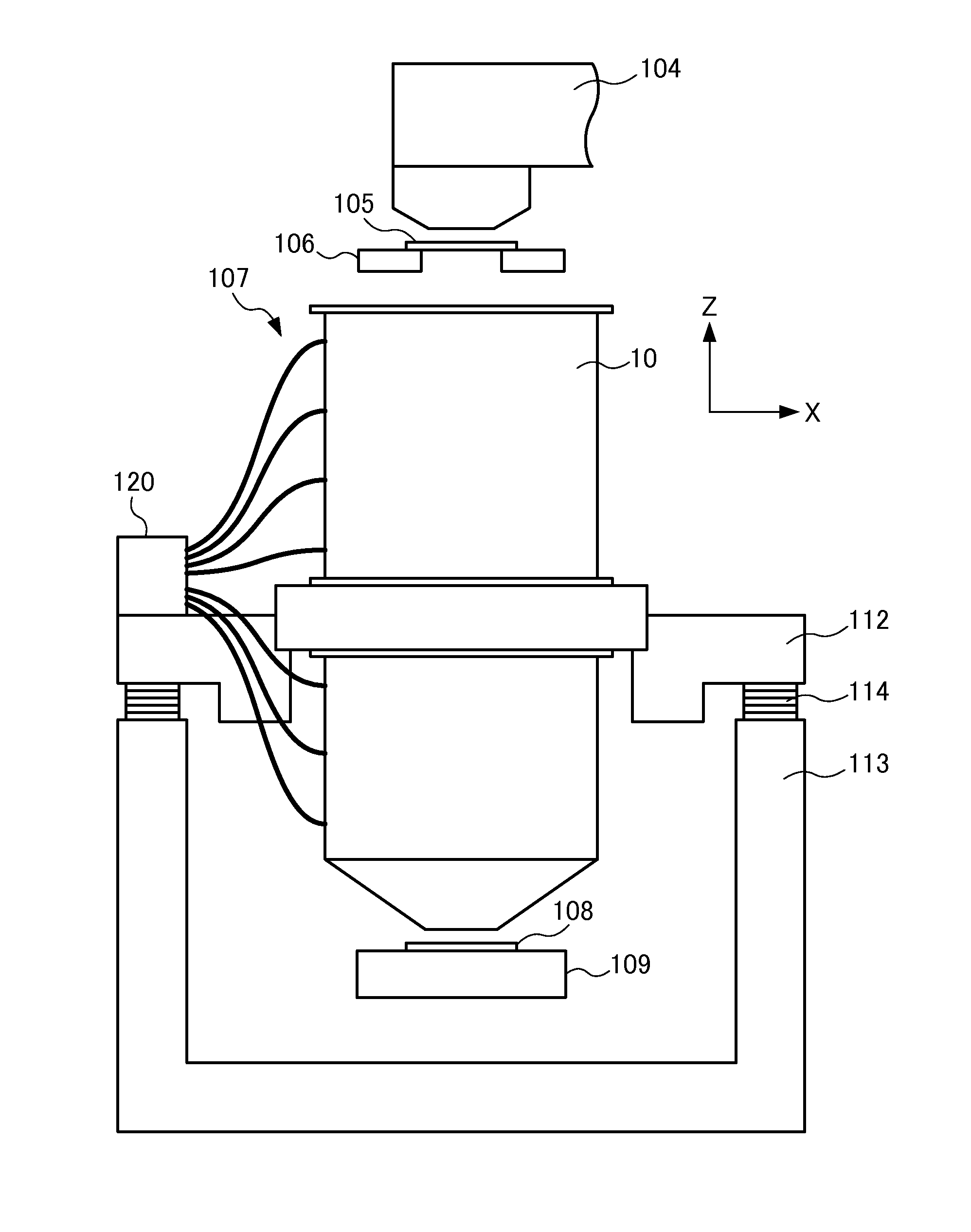
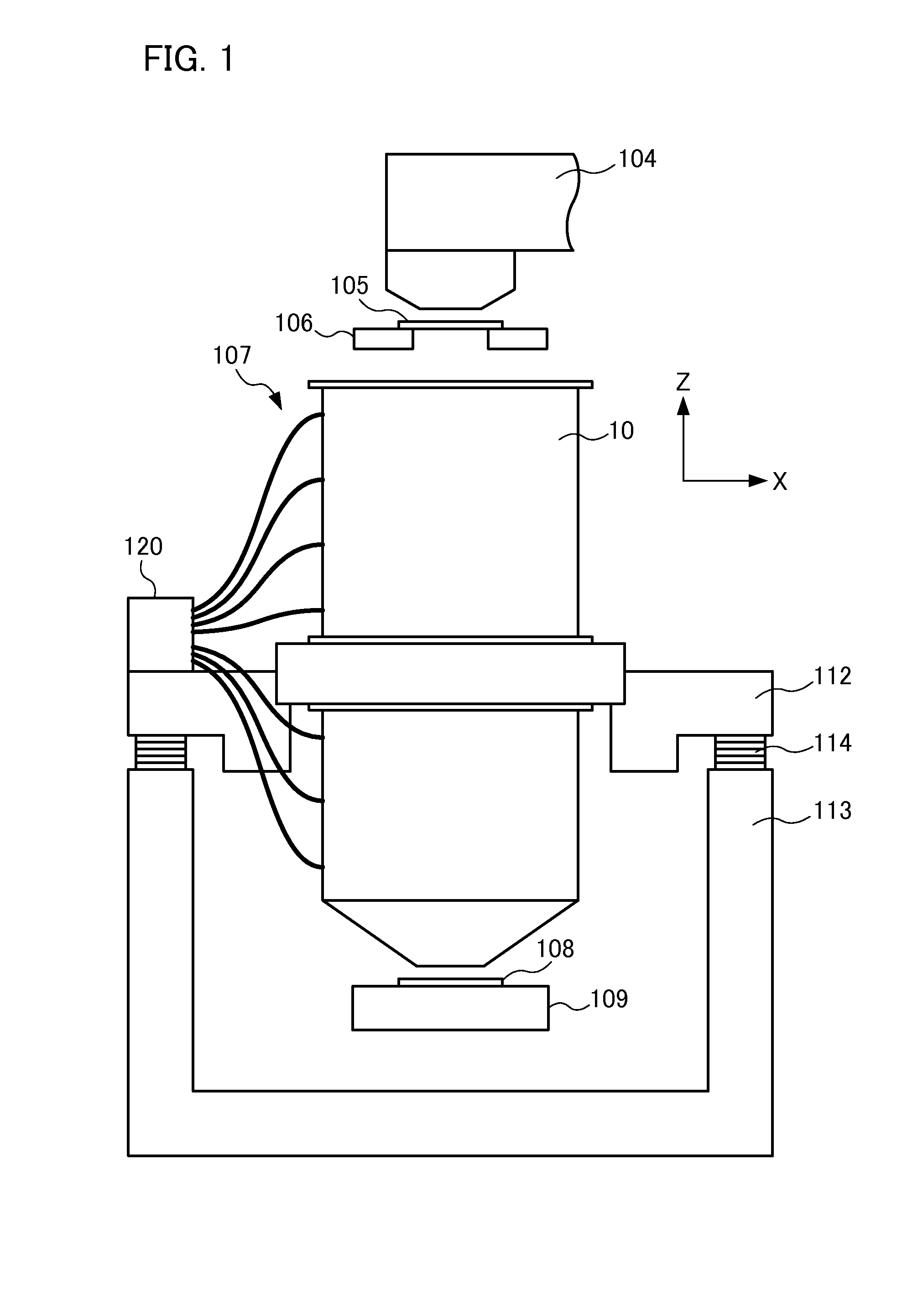
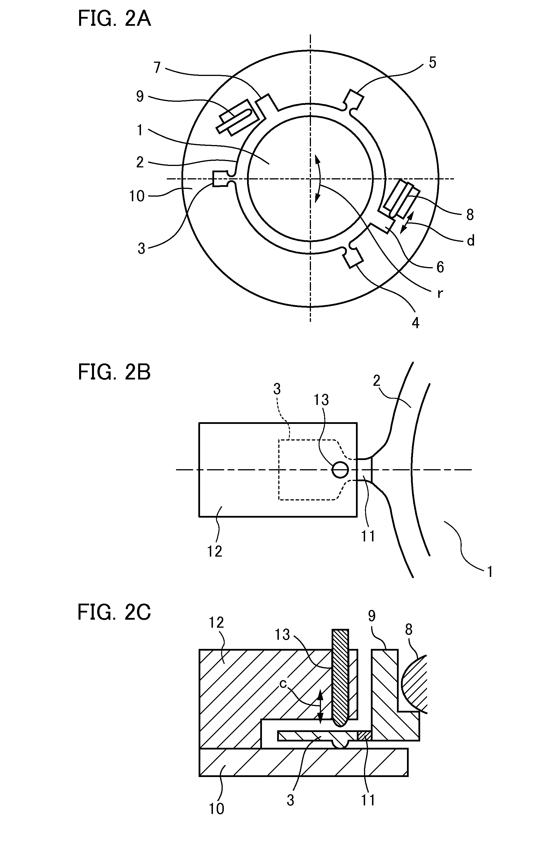
[0025]FIG. 2A is a top plan view illustrating an optical element position adjusting mechanism mounted on the exposure apparatus shown in FIG. 1. The optical element position adjusting mechanism is mounted to the terminating face of the optical lens barrel 10 facing the wafer 108 shown in FIG. 1. The optical element position adjusting mechanism includes an optical element 1 and a holding member 2 that holds the outer periphery of the optical element 1. The optical lens barrel 10 serves as a fixing portion for pivotally fixing the holding member 2 in order to adjust the position of the optical element 1. The holding member 2 holds the outer periphery of the optical element 1 using an adhesive, a mechanical fixture, or the like. In the all embodiments described below, a description will be given assuming that the optical element 1 is a projection lens which is used during projection / transfer of the pattern in the optical system of the exposure apparatus. However, the present invention ...

second embodiment

[0042]FIG. 6 is a top plan view illustrating an optical element position adjusting mechanism according to a second embodiment of the present invention. Each of the engagement protrusions 3 to 5 and the pressed protrusions 6, 7, and 20 is provided at a position facing the radial direction of the outer periphery of the holding member 2. The holding member 2 is driven by the similar procedure as that shown in FIG. 5, and thereby the similar effects as that in the first embodiment may be provided. In comparison to the first embodiment, since the pressed protrusions are provided facing the engagement protrusions 3 to 5, the pressed protrusion 20 is added. With the aforementioned facing arrangement, for example, the pivot direction r substantially corresponds to the tangential direction d in the case where the clamping portion 13 (not shown) of the engagement protrusion 3 is fixed to thereby push the pressed protrusion 6 by the driving section 8. Hence, the force imposed on the pressed pr...

third embodiment

[0043]FIG. 7 is a top plan view illustrating an optical element position adjusting mechanism according to a third embodiment of the present invention. The arrangement of the engagement protrusions 3 to 5 and the pressed protrusions 6, 7, and 20 is the same as that shown in FIG. 6. The driving sections 8, 9, and 21 are provided such that they push the pressed protrusions 6, 7, and 20 from the radial direction p of the outer periphery of the holding member 2 towards the center thereof.

[0044]FIG. 8A is a flowchart illustrating an optical element position adjusting method (a method for driving an optical element) according to the present embodiment. FIG. 8B is a flowchart illustrating an optical element position adjusting method (a method for deforming an optical element) according to the present embodiment.

[0045]The specific effects obtained by the method to be described in FIG. 8A are substantially the same as those obtained by the method described in FIG. 5. Hence, a brief descriptio...


PUM


Abstract

The optical element position adjusting mechanism includes a holding member for holding an outer periphery of an optical element, a fixing portion for pivotally fixing the holding member to adjust the position of the optical element, a clamping portion capable of fixing or releasing the holding member against the fixing portion, a driving section for driving the holding member fixed to the fixing portion by the clamping portion in a pivot direction, and a flexure that is interposed between the clamping portion and the holding member and elastically deforms to guide the holding member driven by the driving section in the pivot direction about the clamping portion. The holding member positioned by the pivot is released from the fixing portion by the clamping portion to restore the flexure to the state prior to being elastically deformed, whereby it is again fixed to the fixing portion by the clamping portion.

Description

BACKGROUND OF THE INVENTION[0001]1. Field of the Invention[0002]The present invention relates to an optical element position adjusting mechanism and an optical element position adjusting method, an exposure apparatus using the same, and a device manufacturing method.[0003]2. Description of the Related Art[0004]In an exposure apparatus, a superposition of patterns may necessitate a mechanism for adjusting the position of an optical element with high accuracy. As a mechanism for adjusting the position of an optical element, measurements by a sensor and a feedback control using these measurement results have been conventionally employed in order to achieve highly accurate positioning and at the same time to achieve high position stability. Japanese Patent Laid-Open No. 2008-242448 discloses an exposure apparatus having a mechanism which employs in combination a feedback control using a sensor and an actuator, and a flexure guide. In this case, an improvement is made such that the mecha...

Claims


Application Information

Patent Timeline
IPC IPC(8): G02B7/02G03F7/20
CPCG03F7/70825G02B7/023
Inventor IMANISHI, KENICHI
Owner CANON KK
Why Eureka
Try Eureka