
Garment production cutting device

A cutting device and clothing technology, applied in the field of clothing design, can solve the problems of easy loosening of chains, poor fineness, poor cutting effect, etc., and achieve the effect of high position stability, good cutting effect and simple structure

Inactive Publication Date: 2017-07-18
WENZHOU POLYTECHNIC
View PDF5 Cites 1 Cited by
  • Summary
  • Abstract
  • Description
  • Claims
  • Application Information

AI Technical Summary

Problems solved by technology

[0002] Clothing tailoring currently adopts more cutting methods with knives. During the cutting process of the clothing material, the cutting part is opened, and the force is uneven during the cutting process, resulting in damage to the clothing material, and the cutting effect is poor.
Although the above problems can be overcome by using a laser cutting machine, the structure is relatively complicated. The laser travel device adopts a sprocket chain structure, which has poor fineness and the chain is easy to loosen, resulting in a large change in the height of the Z axis.

Method used


Image

  • Garment production cutting device
  • Garment production cutting device
  • Garment production cutting device

Examples


Embodiment Construction

[0012] In order to make the purpose, technical solutions and advantages of the embodiments of the present invention clearer, the technical solutions in the embodiments of the present invention will be clearly and completely described below in conjunction with the drawings in the embodiments of the present invention. Obviously, the described embodiments It is a part of embodiments of the present invention, but not all embodiments. Based on the embodiments of the present invention, all other embodiments obtained by persons of ordinary skill in the art without creative efforts fall within the protection scope of the present invention.

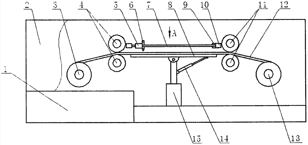
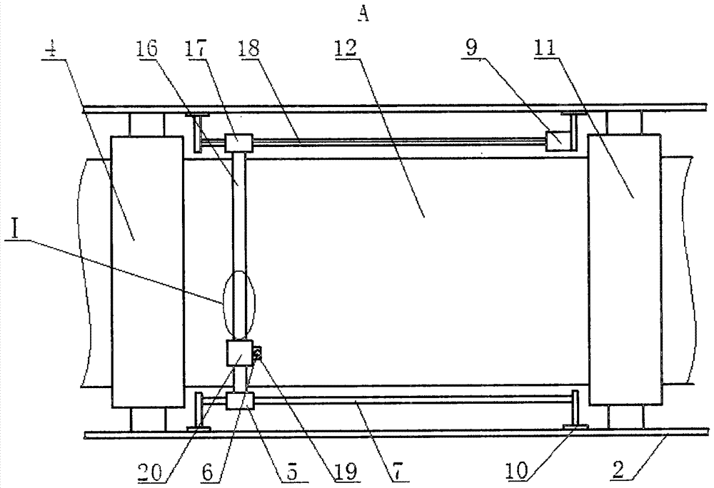
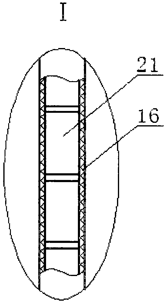
[0013] Clothing production and cutting device, as shown in the figure, includes two side plates 2, and between the side plates 2, there are a raw material roll 3, a front pinch roll 4, a rear pinch roll 11, and waste materials with rotating power. Roller 13, the side plate 2 place between front pinch roller 4 and rear pinch roll 11 is provided wit...


PUM


Abstract

The invention discloses a garment producing and cutting device. The garment producing and cutting device comprises two side plates. A raw material roller, front pressing rollers, rear pressing rollers and a scrap roller with rotation power are sequentially arranged between the side plates. Supporting bases are arranged in the positions, between the front pressing rollers and the rear pressing rollers, of the side plates. A guide rod is arranged on the supporting bases of one side plate, and a sliding base is arranged on the guide rod. A lead screw is arranged on the supporting bases of the other side plate, one end of the lead screw is connected with an output shaft of a motor, and the other end of the lead screw is matched with the supporting bases through bearings. A nut is arranged on the lead screw in a matched mode. The lead screw is parallel to the guide rod. A sliding sleeve is arranged between the nut and the sliding base. A metal sliding block is arranged on the sliding sleeve in a matched mode. A plurality of electromagnets are arranged in the sliding sleeve in sequence. A chuck is mounted on the metal sliding block. A laser is mounted on the chuck. A metal liner plate is arranged on the lower portion of the laser. The lead screw and the nut are adopted as a travelling structure in the X-axis direction, the fineness is high, deformation is not caused by long-time using, the height position of the laser is stable, and the multiple electromagnets are adopted in the Y-axis direction.

Description

technical field [0001] The invention belongs to the field of clothing design, in particular to a clothing production and cutting device. Background technique [0002] Clothing cutting currently adopts more cutting methods with knives. During the cutting process of clothing materials, the cutting place opens, and the uneven force in the cutting process causes damage to the clothing materials, and the cutting effect is poor. Although the above problems can be overcome by using a laser cutting machine, the structure is relatively complicated. The laser traveling device adopts a sprocket chain structure, which has poor fineness and the chain is easy to loosen, resulting in a large change in the Z-axis height. Contents of the invention [0003] The invention provides a clothing production and cutting device to solve the defects in the prior art. [0004] The present invention is achieved through the following technical solutions: [0005] Clothing production cutting device, i...

Claims


Application Information

Patent Timeline
Patent Type & Authority Patents(China)
IPC IPC(8): B23K26/38B23K26/08B23K26/70
CPCB23K26/0876B23K26/38B23K26/702
Inventor 吴国智
Owner WENZHOU POLYTECHNIC
Learn More