
Industrial Automatic Object Transportation System and Operation Method of the Same

a technology of automatic object transportation and operation method, which is applied in the direction of process and machine control, distance measurement, instruments, etc., can solve the problems of manual operation of forklift trucks, insufficient attention to and inability to completely solve the problem of manpower and labor costs

Inactive Publication Date: 2010-11-25
DA-YEH UNIVERSITY
View PDF5 Cites 59 Cited by
  • Summary
  • Abstract
  • Description
  • Claims
  • Application Information

AI Technical Summary

Benefits of technology

[0009]An object of the present invention is to provide an industrial automatic object transportation system so as to automatically transport objects (such as goods), which lowers labor cost and presets environment coordinates accommodating indoor or outdoor applications.

Problems solved by technology

Although using the forklift trucks to transport objects mitigates manpower and labor costs when it is compared with using labor to manually move the objects, the forklift truck still needs an operator to manipulate.
Hence, problem of manpower and labor costs are not completely addressed.
Further, manual operation of the forklift trucks may lift the wrong objects, transport the objects to wrong destinations, or hurt someone when the operator makes some mistakes or distractions in operations.
Although some factories use tracks on which transportation vehicles move to transport the objects to eliminate the problems of manual operations of the forklift trucks, the cost of building the track systems is expensive, and a track only can be use to transport for one kind of objects.
For companies with different products, using the track system with the transportation vehicles to move the objects is not favorable.

Method used


Image

  • Industrial Automatic Object Transportation System and Operation Method of the Same
  • Industrial Automatic Object Transportation System and Operation Method of the Same
  • Industrial Automatic Object Transportation System and Operation Method of the Same

Examples


Embodiment Construction

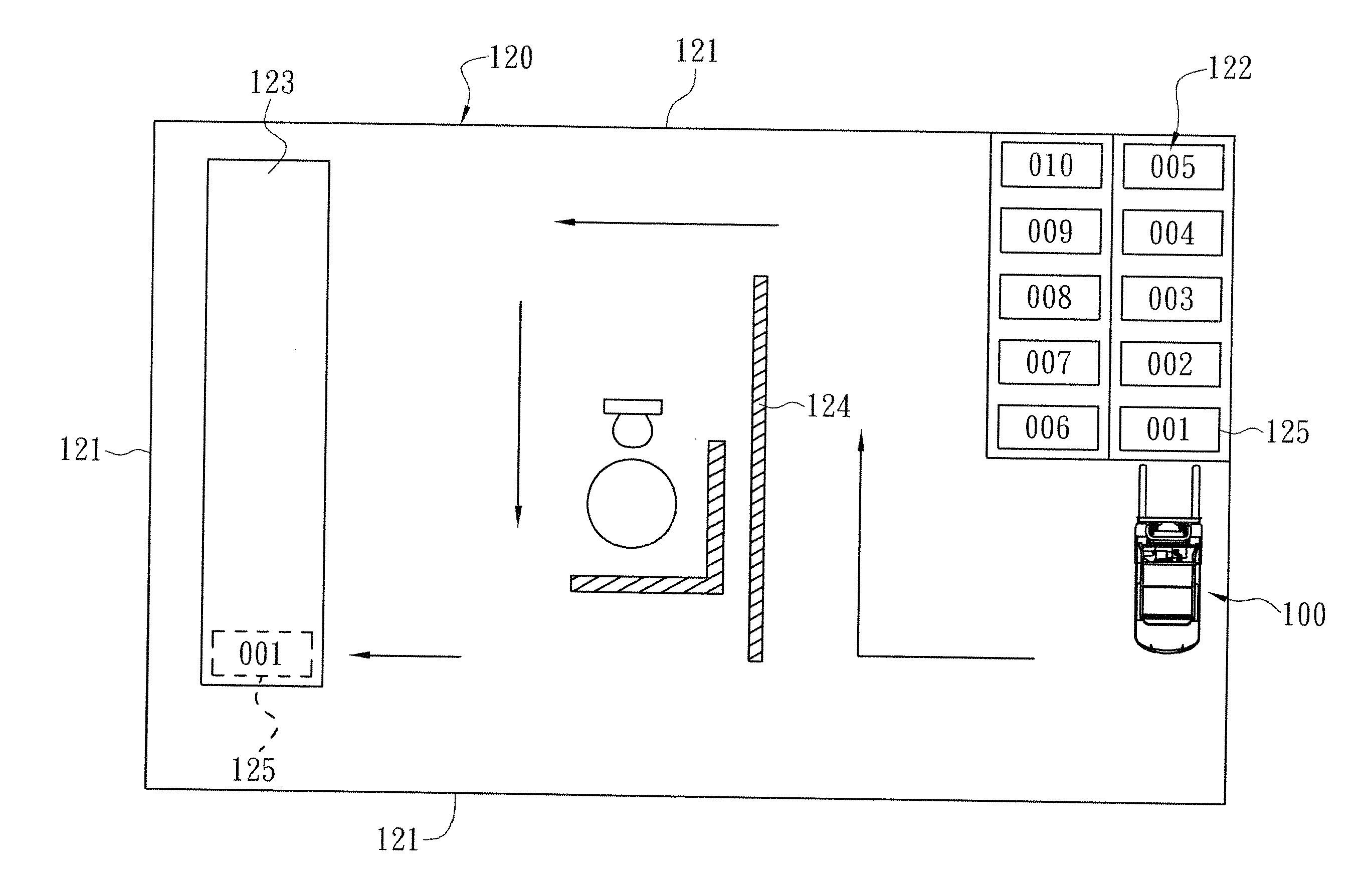
[0025]Reference will now be made in detail to the present preferred embodiments of the invention, examples of which are illustrated in the accompanying drawings. Wherever possible, the same reference numbers are used in the drawings and the description to refer to the same or like parts.

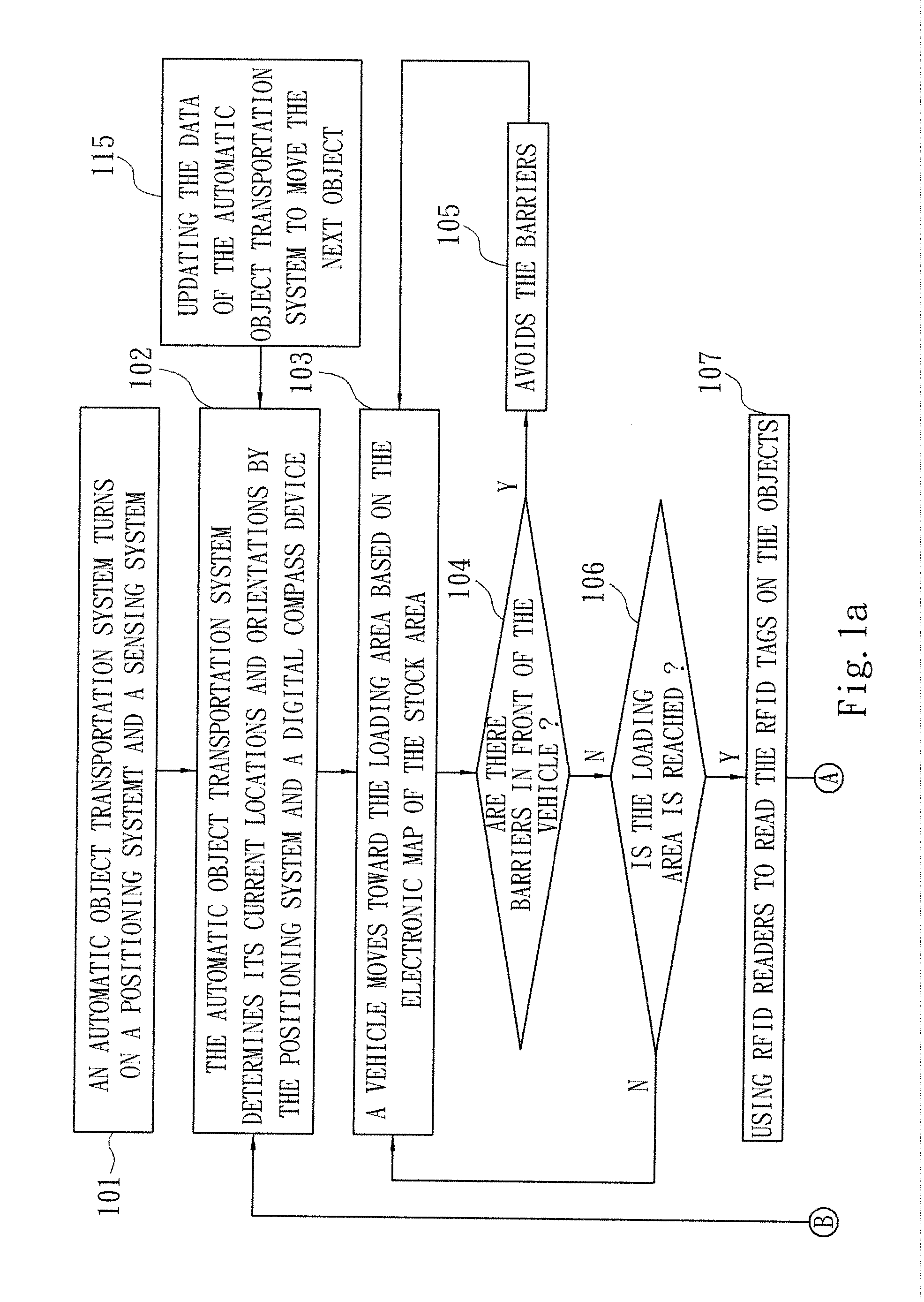
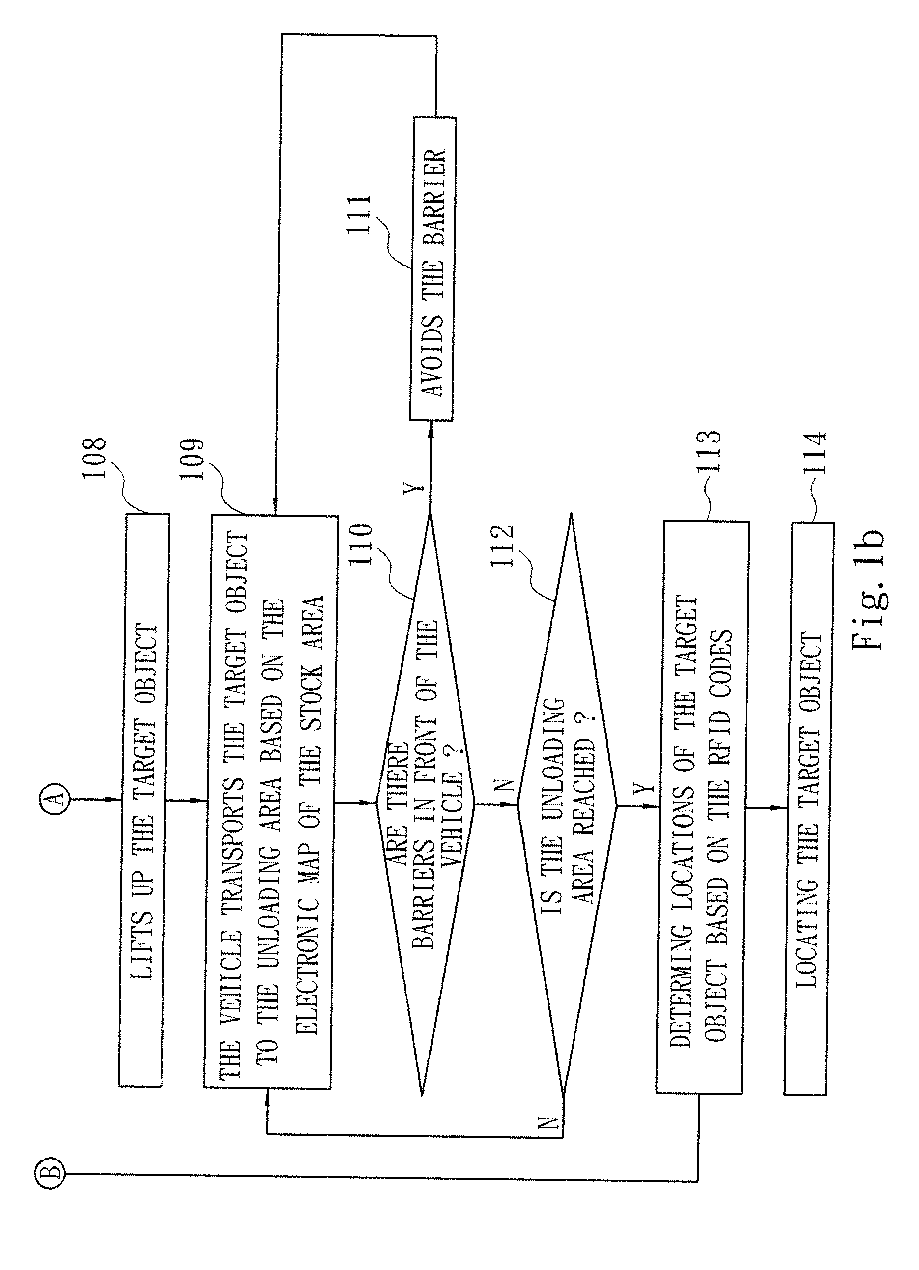
[0026]Refer to FIG. 1a, FIG. 1b and FIG. 2. An operation method of an industrial automatic object transportation system comprises steps as follow.

[0027]In Step A, a positioning system and a sensing system of an industrial automatic object transportation system are turned on when the automatic object transportation system enters an operation state as shown in step 101 and step 102. The automatic object transportation system determines by itself its current locations and orientations using the positioning system and a digital compass device. The positioning system performs procedures comprising setting environment (i.e. a stock area 120), setting reference positioning coordinates, setting positions of ...


PUM


Abstract

An operation method of an industrial automatic object transportation system includes: determining current positions and orientations of a vehicle by a positioning system and a digital compass device of the industrial automatic object transportation system when the industrial automatic object transportation system is kept in an operation state; moving the vehicle toward a loading area where a plurality of objects are located based on an electronic map of a stock area; scanning the objects to identify a target object and lifting up the target object when the vehicle reaches the loading area; moving the vehicle with the target object toward an unloading area based on the electronic map of the stock area; and determining an unloading location of the target object based on RFID codes of the target object to unload the target object at the unloading location when the vehicle reaches the unloading area.

Description

RELATED APPLICATIONS[0001]The application claims priority to Taiwan Application Serial Number 97103302, filed Jan. 29, 2008, which is herein incorporated by reference.BACKGROUND[0002]1. Field of the Invention[0003]The present invention relates to a robotic apparatus. More particularly, the present invention relates to an industrial automatic vehicle and an operation method of the vehicle, and the vehicle automatically transports objects such as goods and materials to given destinations or locations.[0004]2. Description of Related Art[0005]Typically, forklift trucks are used to unload objects such as goods, materials, and cargo from a train or a truck, and move and transport the objects to destinations such as storehouses or working places.[0006]Although using the forklift trucks to transport objects mitigates manpower and labor costs when it is compared with using labor to manually move the objects, the forklift truck still needs an operator to manipulate. Hence, problem of manpower...

Claims


Application Information

Patent Timeline
IPC IPC(8): G05D1/02B65G65/00B66F9/075
CPCB60L2260/28B66F9/0755B66F9/063
Inventor KO, CHIEN-HO
Owner DA-YEH UNIVERSITY
Learn More