Pressured syringe for the injection of a viscous liquid through a cannulated surgical screw bone filler adapter

a technology of surgical screw and syringe, which is applied in the field of pressured syringe for the injection of viscous liquid through the cannulated surgical screw bone filler adapter, can solve the problems of difficult repair, large void or extremely porous space in the head, and fixation problem, and achieve the effect of better fixing the bone repair

Inactive Publication Date: 2010-11-25
JORDAN CHRISTOPHER
View PDF4 Cites 9 Cited by
  • Summary
  • Abstract
  • Description
  • Claims
  • Application Information

AI Technical Summary

Benefits of technology

[0016]Filling a bone void to provide a more stable anchoring matrix would provide a more secure anchoring of a surgical screw, requiring fewer screws and providing a better fixation of the bone repair. As a screw is already being used for this procedure, providing the screw as an already available cannulated surgical screw would require no additional surgical procedure than already being done. The cannulated screw, having already been inserted into a drilled location through the bone, is already located with the tip of the surgical screw in the area where the bone void is presented, already places the tip of the surgical screw in an ideal location which has already been interrupted for the placement of a bone filler cement within the bone void of the bone being repaired. The syringe and adapter are employing the already used cannulated surgical screw as a port for the injection of bone cement through the longitudinal channel directed to the tip of the surgical screw, after having fully inserted the surgical scre

Problems solved by technology

This repair is a difficult repair and ordinarily requires a surgical intervention.
As a person get older, this inner portion of the head becomes more porous and eventually creates a large void or extremely porous space within the head.
This poses a fixation problem for the placement and secure anchoring of a surgical screw inserted within the drilled pathway.
However, this process has not been used in the past for repair or reduction of the reattachment of the end of a bone using surgical screws.
Currently there is no technique or procedure disclosing the use of a cannulated screw as a

Method used


Image

  • Pressured syringe for the injection of a viscous liquid through a cannulated surgical screw bone filler adapter
  • Pressured syringe for the injection of a viscous liquid through a cannulated surgical screw bone filler adapter
  • Pressured syringe for the injection of a viscous liquid through a cannulated surgical screw bone filler adapter

Examples


Embodiment Construction

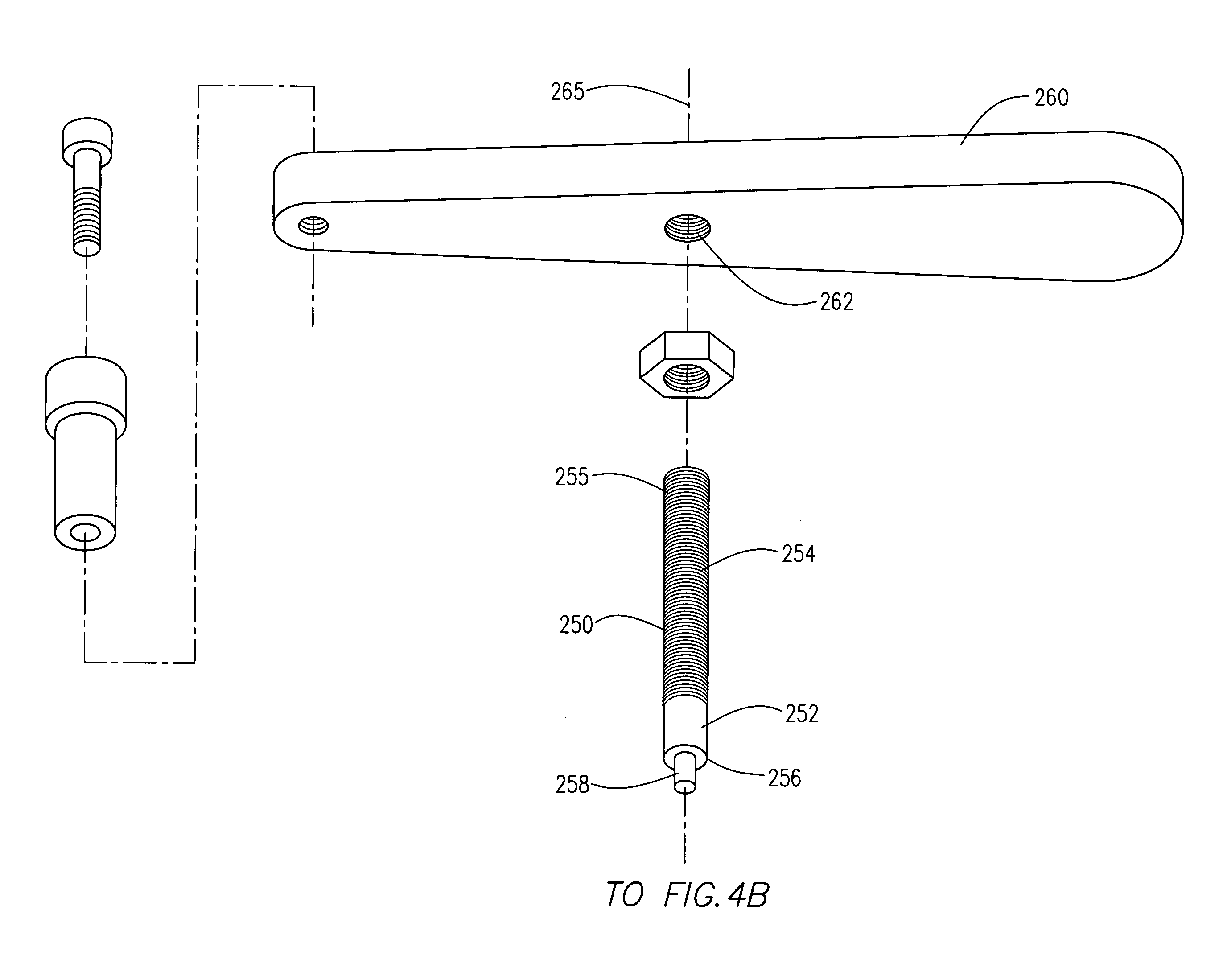
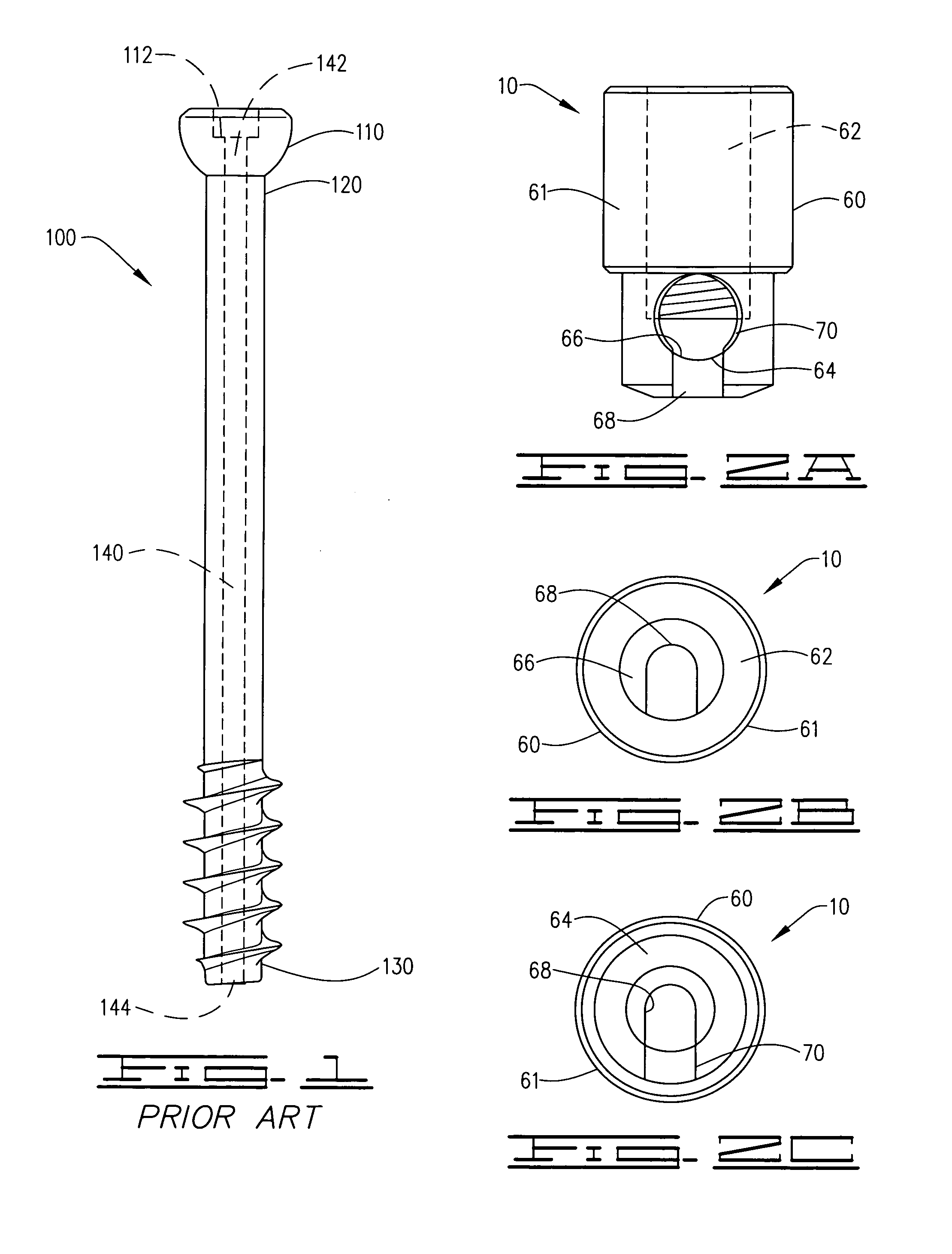
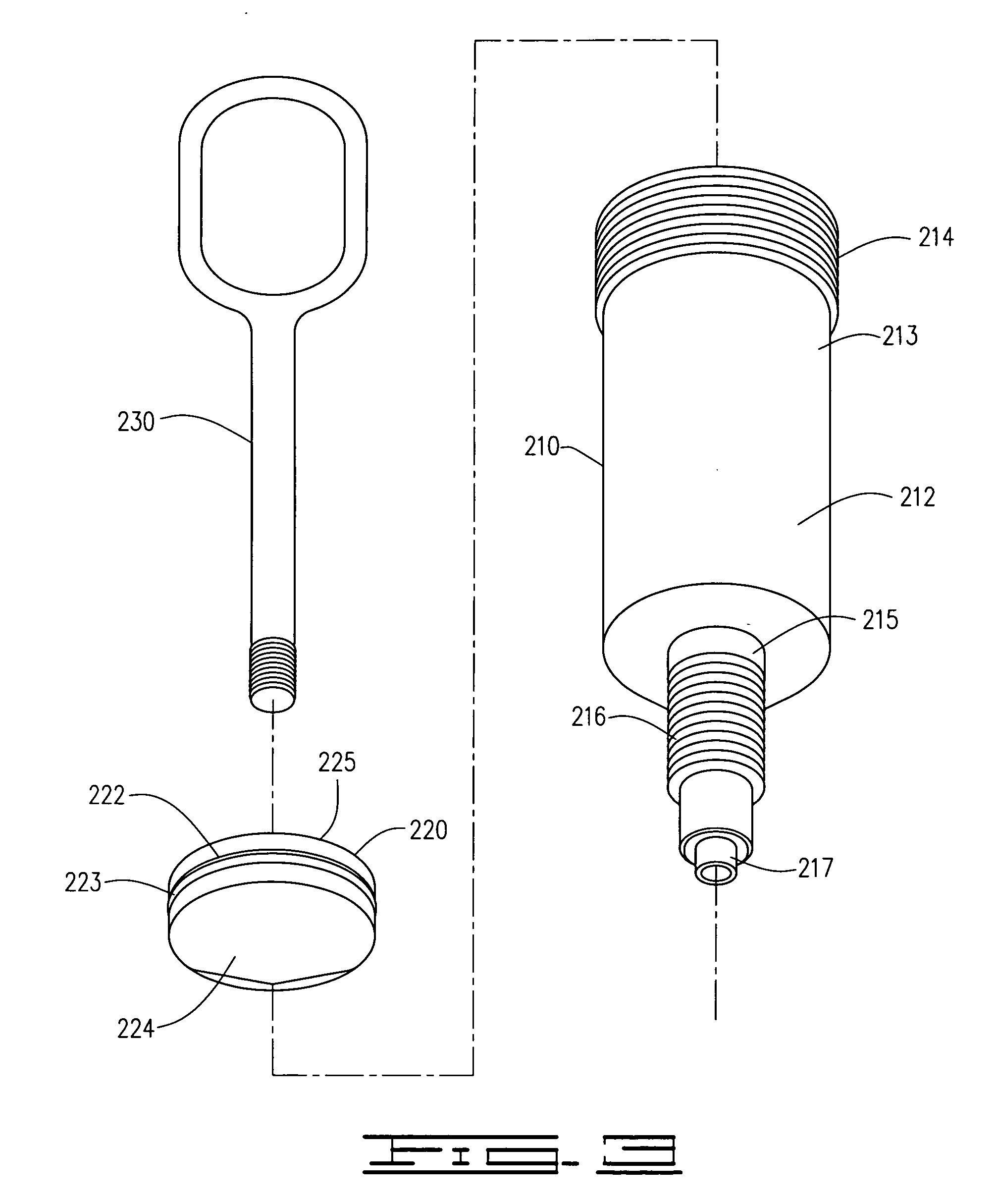
[0032]A pressurized syringe assembly 200 to dispense a high viscous liquid, preferably a bone filler cement, attached to an adapter 10 providing a secure connection between a head 110 of an externally threaded cannulated surgical screw 100, indicated in FIG. 1, 4B, 5B and6B, defining the head 110, neck 120 and tip 130, to inject a bone filler cement through an upper end 142 of a longitudinal bore 140 in the cannulated surgical screw 100 through a lower end 144 of the longitudinal bore 140 into a bone void z within a bone x undergoing a surgical repair at a fracture site y, FIGS. 7A-B, the pressurized syringe assembly 200, FIGS. 3-6B, providing a syringe body 210 defining an inner cavity 211, an upper body portion 212 having an upper end 213 defining a plurality of upper external threads 214 and a lower narrowed body portion 215 including external threads 216 and defining a terminal cannulated screw insertion nipple 217 upon which is inserted an O-ring seal member 218, a thickened pl...


PUM


Abstract

A pressurized syringe used to inject a viscous liquid through an adapter attached to a bone filler adapter into a cannulated surgical screw utilizing the cannulated surgical screw as a port to inject bone void filler into a bone void within a bone cavity during the course of a surgical repair to attach, repair and secure broken or separated bone fragments and providing a more secure bone anchor matrix within which the surgical screw is set.

Description

CROSS REFERENCE TO RELATED APPLICATIONS[0001]This is a Continuation-in-Part Application of U.S. patent application Ser. No. 12 / 454,696, filed by the same inventors on May 21, 2009, with reference made to pending U.S. patent application Ser. No. 12 / 456,577 filed on Jun. 18, 2009 by at least one common inventor, Christopher Jordan.I. BACKGROUND OF THE INVENTION[0002]1. Field of Invention[0003]A pressurized syringe used to inject a viscous liquid through an adapter attached to a bone filler adapter into a cannulated surgical screw utilizing the cannulated surgical screw as a port to inject bone void filler into a bone void within a bone cavity during the course of a surgical repair to attach, repair and secure broken or separated bone fragments and providing a more secure bone anchor matrix within which the surgical screw is set.[0004]2. Description of Prior Art[0005]A preliminary review of prior art patents was conducted by the applicant which reveal no prior art patents in a similar ...

Claims


Application Information

Patent Timeline
IPC IPC(8): A61F2/56
CPCA61B17/7098A61B17/8822A61B17/864
Inventor JORDAN, CHRISTOPHER
Owner JORDAN CHRISTOPHER
Why Eureka
Try Eureka