Apparatus for determining cut resistance

a technology of apparatus and resistance, applied in the direction of instruments, apparatus for force/torque/work measurement, and investigations of machinability, etc., can solve the problem of not addressing the need for an apparatus and a method

Active Publication Date: 2010-12-02
DUPONT SAFETY & CONSTR INC
View PDF12 Cites 24 Cited by
  • Summary
  • Abstract
  • Description
  • Claims
  • Application Information

AI Technical Summary

Problems solved by technology

However, these references do not address the need for an apparatus and method for testing the cut resistance of automobile tire sidewalls that are in tension as a result of tire inflation pressure.

Method used


Image

  • Apparatus for determining cut resistance
  • Apparatus for determining cut resistance
  • Apparatus for determining cut resistance

Examples


Embodiment Construction

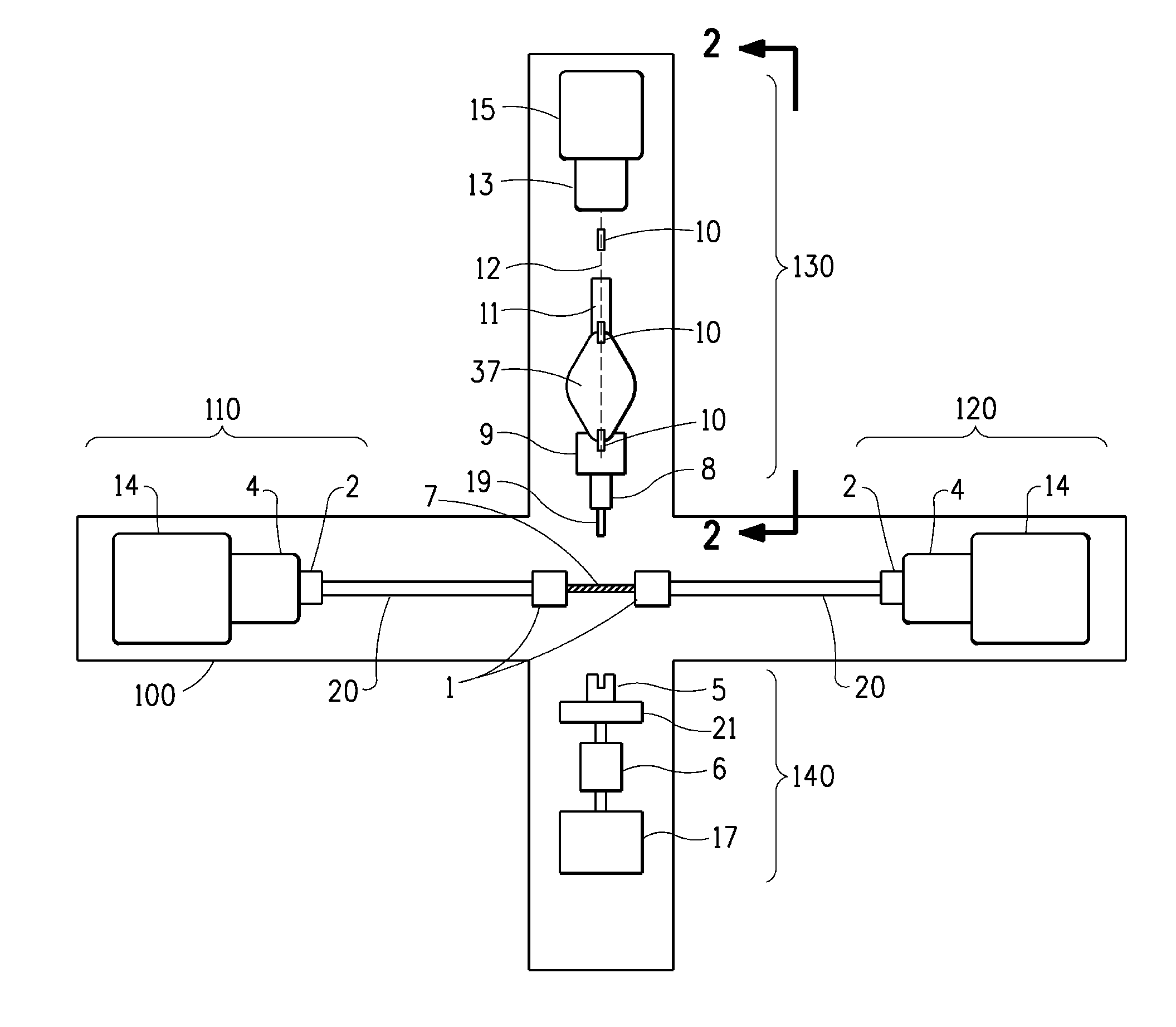
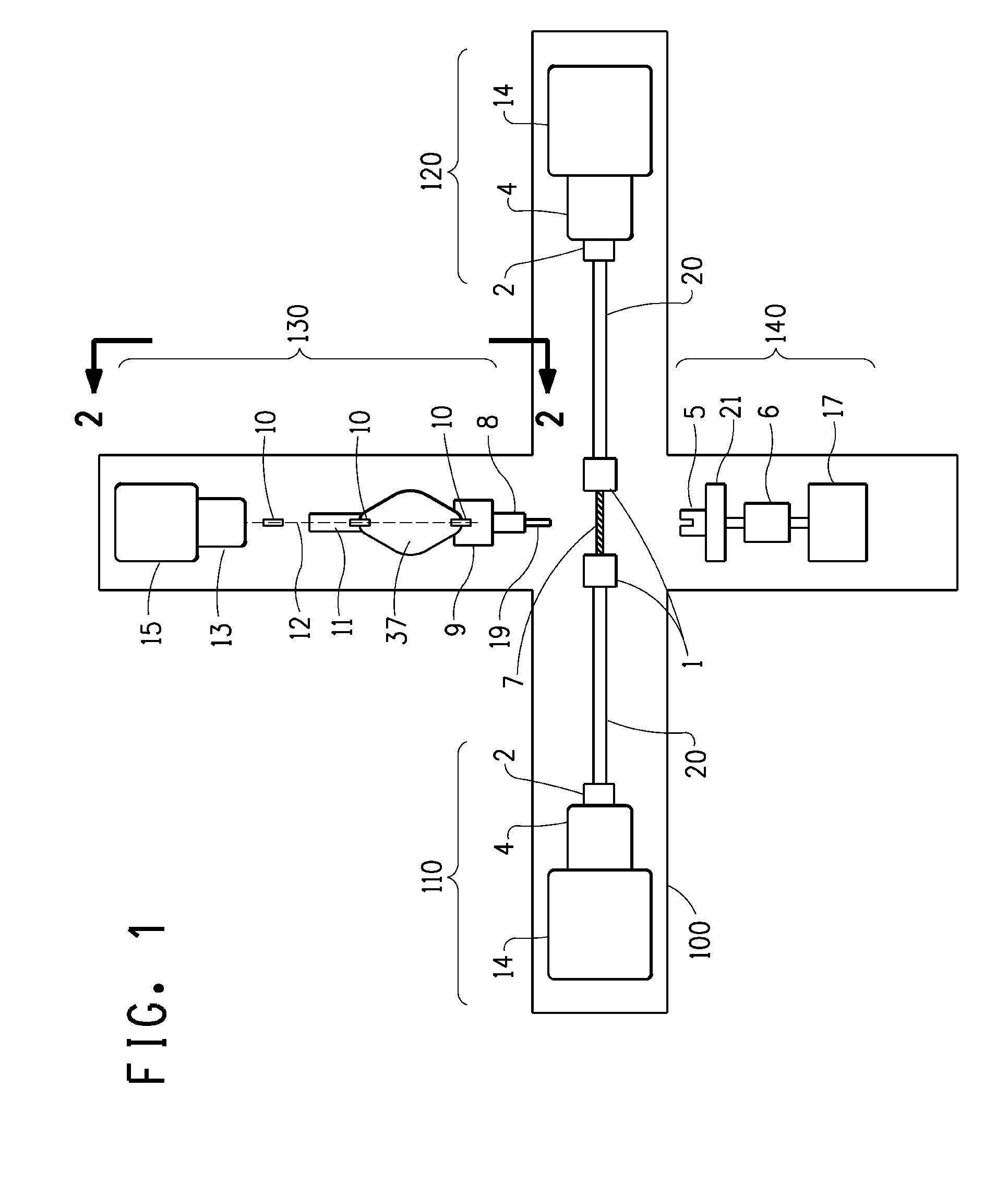
[0007]This invention is directed to an apparatus and method of using the apparatus for measuring the cut resistance of polymeric and elastomeric materials under conditions that closely simulate those found in field use. As an example, automobile tire sidewalls are in tension as a result of tire inflation pressure. The apparatus described herein permits elastomeric specimens representing the sidewall to be cut while under tension that simulates an inflated tire. The apparatus comprises with respect to FIGS. 1 and 2

[0008](a) first and second specimen holding and tensioning devices 110 and 120 arranged on a common axis wherein the tensioning devices each comprise an assembly of components connected together in the sequential order of test specimen grips 1, connecting rods 20, release couplings 2, load cells 4 and actuators 14,

[0009](b) a cutting device 130 located orthogonally to the axis of the first and second specimen tensioning devices wherein the cutting device further comprises a...


PUM

PropertyMeasurementUnit
cut resistanceaaaaaaaaaa
flexibleaaaaaaaaaa
tensionaaaaaaaaaa

Abstract

An apparatus and a method of using the apparatus for measuring the cut resistance of polymeric and elastomeric materials having specimen holding and tensioning devices arranged on a common axis; a blade cutting device located orthogonally to the axis of the first and second specimen tensioning devices and a cutting block assembly located on the same axis as the cutting device and on the opposite side of the specimen tensioning device.

Description

BACKGROUND OF THE INVENTION1. Field of the Invention[0001]This invention relates to an apparatus for determining the cut resistance of materials under tension[0002]2. Description of the Related Art[0003]U.S. Pat. No. 5613414 describes a device that employs a heated knife for cutting elastomeric materials such as those used for tire treads. US patent Publication 2008 / 0073020 describes an apparatus and method for cutting elastomeric components in the tire building process. U.S. Pat. No. 4,864,852 describes an apparatus and method to cut flexible materials used in protective apparel. However, these references do not address the need for an apparatus and method for testing the cut resistance of automobile tire sidewalls that are in tension as a result of tire inflation pressure.BRIEF DESCRIPTION OF THE DRAWINGS[0004]FIG. 1 is an overall-view of the testing machine.[0005]FIG. 2 is a side view of the blade holder and related support.[0006]FIG. 3 is a view of a cutting block against which ...

Claims


Application Information

Patent Timeline
Patent Type & Authority Applications(United States)
IPC IPC(8): G01N3/56
CPCG01N3/58G01N2203/0278G01N2203/0003G01N33/442
Inventor COULTER, WILLIAM HERBERTLAMONTIA, MARK ALLAN
Owner DUPONT SAFETY & CONSTR INC
Why Eureka
Try Eureka