
Hydraulic pressure multiplier

Inactive Publication Date: 2010-12-02
LAMBERT BRAKE
View PDF4 Cites 0 Cited by
  • Summary
  • Abstract
  • Description
  • Claims
  • Application Information

AI Technical Summary

Benefits of technology

[0006]It is thus an object of one aspect of the present invention to provide a hydraulic pressure multiplier that is simple and economical.
[0007]It is an object of another aspect of the present invention to provide a hydraulic pressure multiplier, as above, that provides an increase in fluid pressure without requiring a substantial increase in fluid volume.
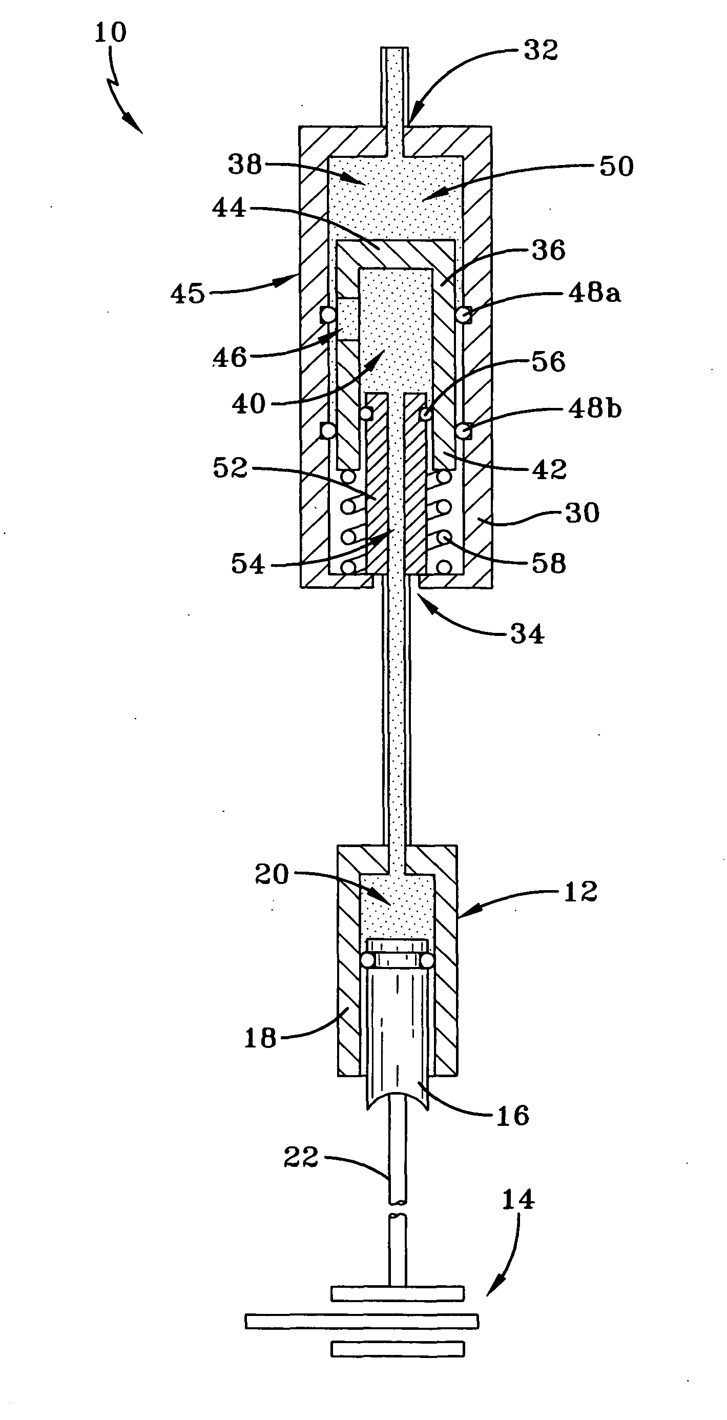
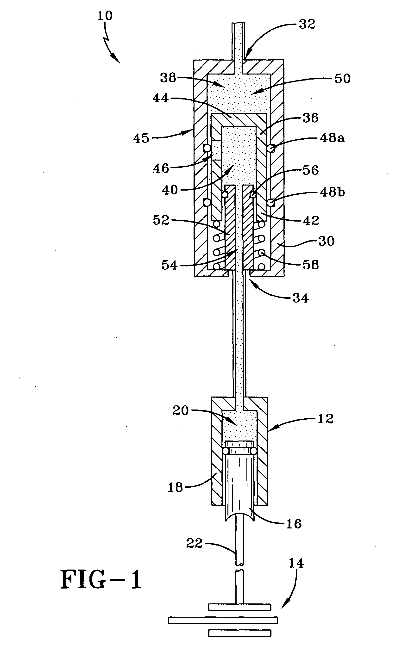
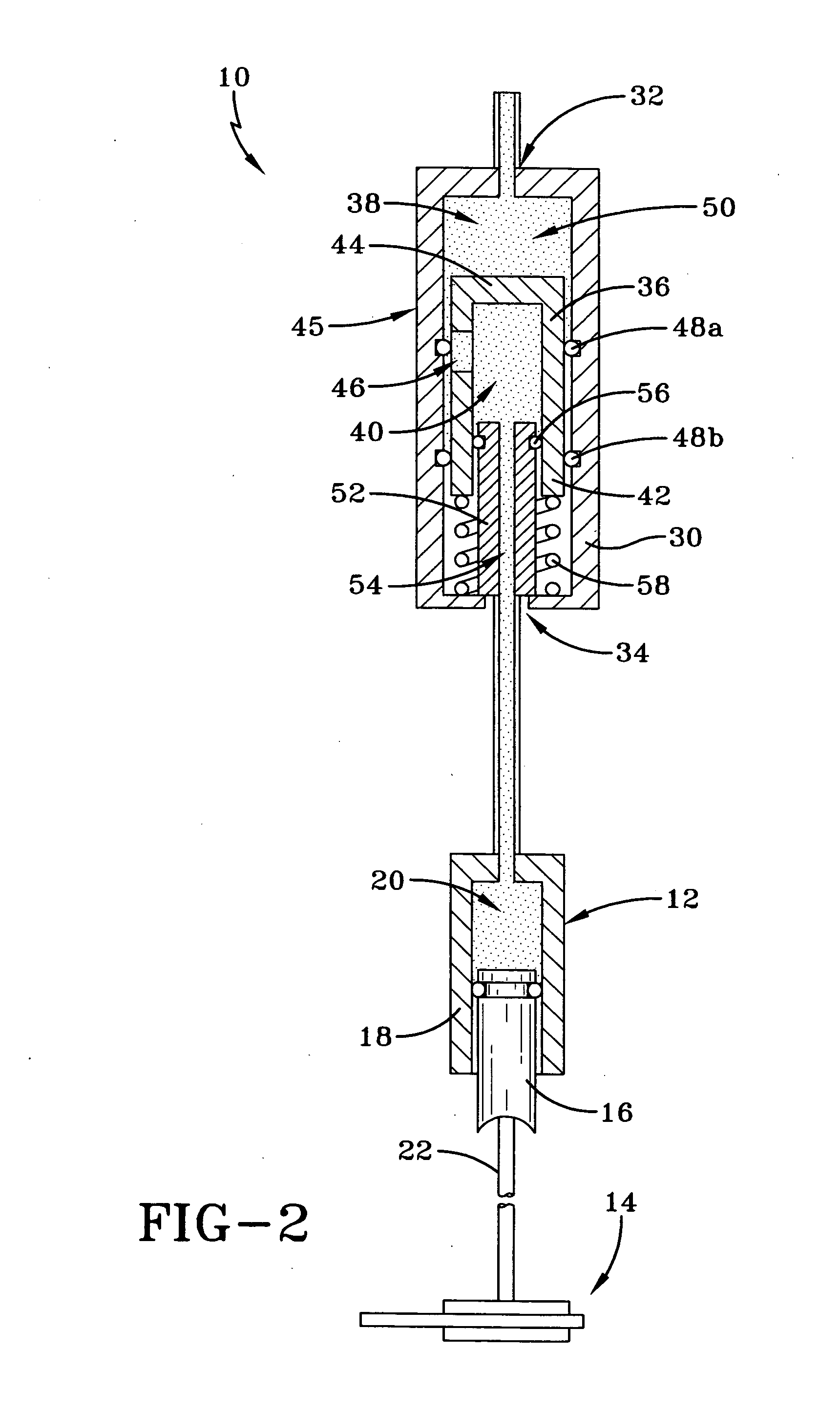
[0009]In general, a hydraulic pressure multiplier according to the concepts of the invention includes a housing defining an inner cavity. An outer piston is movably positioned within the inner cavity and includes a sidewall and an end wall that together define an inner recess having an open end. A stationary inner piston is received in the open end of the inner recess in the outer piston, and a bore is provided through the inner piston. An opening through the outer piston is in fluid communication with the inner cavity and the inner recess to allow fluid flow therebetween. A biasing mechanism applies a biasing force to the outer piston, and a valve mechanism is movable between an open position and a closed position. The valve mechanism prevents fluid flow through the opening in the outer piston when it is in the closed position.
[0010]In accordance with another aspect of the present invention, a hydraulic pressure multiplier includes a housing defining an inner cavity, an inlet port in fluid communication with the inner cavity: an outlet port; an outer piston slidably positioned within the inner cavity and including a sidewall and an end wall; an inner recess defined by the sidewall and the end wall of the outer piston, the inner recess having an open end; a gasket positioned around the outer piston and within the inner cavity; a stationary inner piston positioned at least partially within the inner recess in the outer piston; an inner bore extending through the inner piston and in fluid communication with the inner recess and the outlet port; a gasket positioned around the inner piston and within the inner recess of the outer piston; a biasing mechanism that biases the outer piston toward the inlet port; an opening through the outer piston; and a valve mechanism that selectively prevents fluid flow through the opening.

Problems solved by technology

Frequently, however, a master cylinder alone cannot meet the force and volume requirements of hydraulically actuated off-highway braking systems.
Conversely, when the master cylinder is adapted to provide high-pressure fluid, then it is usually incapable of providing the high volume of fluid necessary to generate sufficient braking force.
Hydraulic power boosters are well known in the art and are commercially available from several manufacturers, but they are also relatively expensive.
This solution is both expensive and complicated, and is therefore not ideal.

Method used


Image

  • Hydraulic pressure multiplier
  • Hydraulic pressure multiplier
  • Hydraulic pressure multiplier

Examples


Embodiment Construction

[0021]One embodiment of a hydraulic pressure multiplier made in accordance with the present invention is shown in FIGS. 1-3 and is indicated generally by the numeral 10. Pressure multiplier 10 may be installed and positioned inline between a master cylinder (not shown) and a slave cylinder 12 or other hydraulic piston in a brake assembly.

[0022]Slave cylinder 12 is adapted to actuate a braking assembly schematically indicated by the numeral 14. It is also contemplated, however, that pressure multiplier 10 may be incorporated into the master cylinder housing or into the brake body. Slave cylinder 12 may be any slave cylinder known to those skilled in the art, and includes a piston 16 slidably received in a bore in body 18, and a fluid chamber 20. A piston rod 22 extends from slave cylinder piston 16 to engage or otherwise actuate brake assembly 14.

[0023]Brake assembly 14 may be any brake assembly known to those skilled in the art and adapted to be actuated by a slave cylinder. It is a...


PUM


Abstract

A hydraulic pressure multiplier having a housing, a bore in the housing and an outer piston slidably positioned within the bore. The pressure multiplier also includes an inner piston having a bore therethrough, the inner piston being positioned within a bore within the outer piston. An opening is provided through an end wall of the outer piston, and a mechanism is provided to selectively control hydraulic fluid flow into the bore within the outer piston. Hydraulic fluid first flows through the opening in the outer piston and through the bore through the inner piston to actuate a slave cylinder or a hydraulic piston within a brake. After a threshold pressure is reached within the slave cylinder, the valve closes and the outer piston is caused to move axially, thereby providing an increased hydraulic pressure within the slave cylinder.

Description

[0001]This application claims priority from U.S. provisional patent application Ser. No. 61 / 217,560 filed on Jun. 2, 2009, which is incorporated herein by reference in its entirety.TECHNICAL FIELD[0002]This invention relates to a hydraulic pressure multiplier particularly useful in braking systems. More specifically, this invention relates to such a hydraulic pressure multiplier adapted to be installed inline between a master cylinder and a slave cylinder, the pressure multiplier including two concentric pistons.BACKGROUND ART[0003]Off-highway braking systems often utilize a master cylinder to provide a hydraulic actuating mechanism. The master cylinder, when actuated, supplies high pressure fluid to a slave cylinder, which actuates the braking mechanism. Frequently, however, a master cylinder alone cannot meet the force and volume requirements of hydraulically actuated off-highway braking systems. Such systems require both a large volume of fluid as well as high pressure fluid in o...

Claims


Application Information

Patent Timeline
IPC IPC(8): B60T13/135
CPCF15B3/00B60T13/165
Inventor CHANDLER, EDWARD L.
Owner LAMBERT BRAKE
Learn More