
Print apparatus, print method, and print program

Inactive Publication Date: 2010-12-02
SONY CORP
View PDF7 Cites 4 Cited by
  • Summary
  • Abstract
  • Description
  • Claims
  • Application Information

AI Technical Summary

Benefits of technology

[0013]According to the present invention, in the print apparatus, it is possible to print the image characteristic portion extending in a single direction depicted in the representative image representing the contents recording on the recording disc on one surface of the disc without omission.
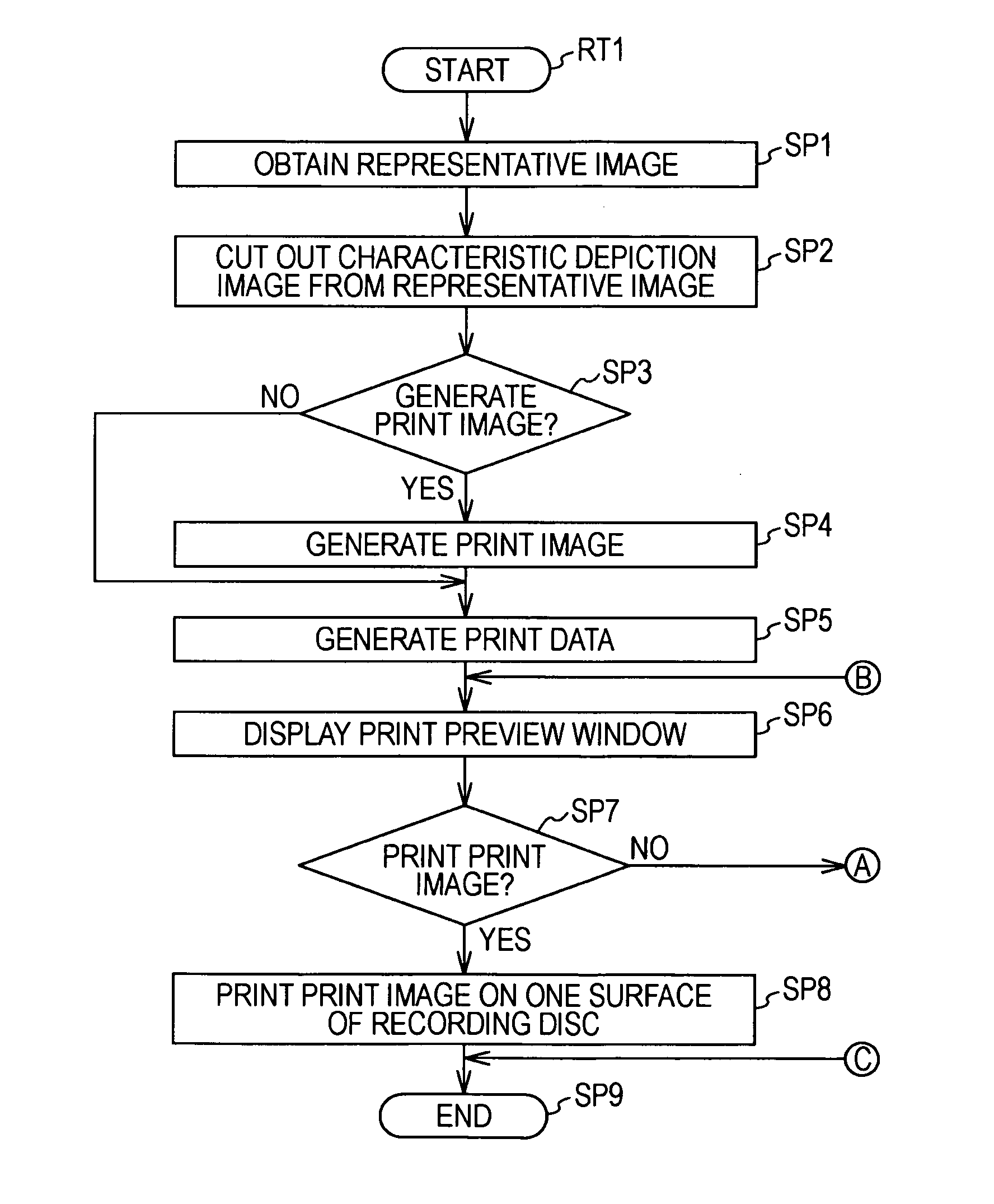
[0014]According to the present invention, in the print apparatus, a circular print image is generated by bonding one end and the other end of a single direction of a representative image where an image characteristic portion extending in a single direction is depicted to represent contents recorded on the recording disc, and the print image is printed on one surface of the recording disc by matching the center of the recording disc with the center of the print image. Thereby, it is possible to print the image characteristic portion extending in one direction, where the representative image representing the recorded contents recorded on the recording disc is depicted, on one surface of the disc without any omission. It is possible to implement the print apparatus, the print method, and the print program capable of identifying the contents recorded in the corresponding recording disc by the print image printed on the recording disc.

Problems solved by technology

Therefore, it is difficult for the print apparatus to print out both the corresponding ends of the image characteristic portion on one surface.
The print apparatus also has a problem in that, if both ends of the image characteristic portion are missing from the recording image printed on one surface of the disc, users may be difficult to identify what kind of recording image has been recorded just by using such a printed content.

Method used


Image

  • Print apparatus, print method, and print program
  • Print apparatus, print method, and print program
  • Print apparatus, print method, and print program

Examples


modification 1

2-1. Modification 1

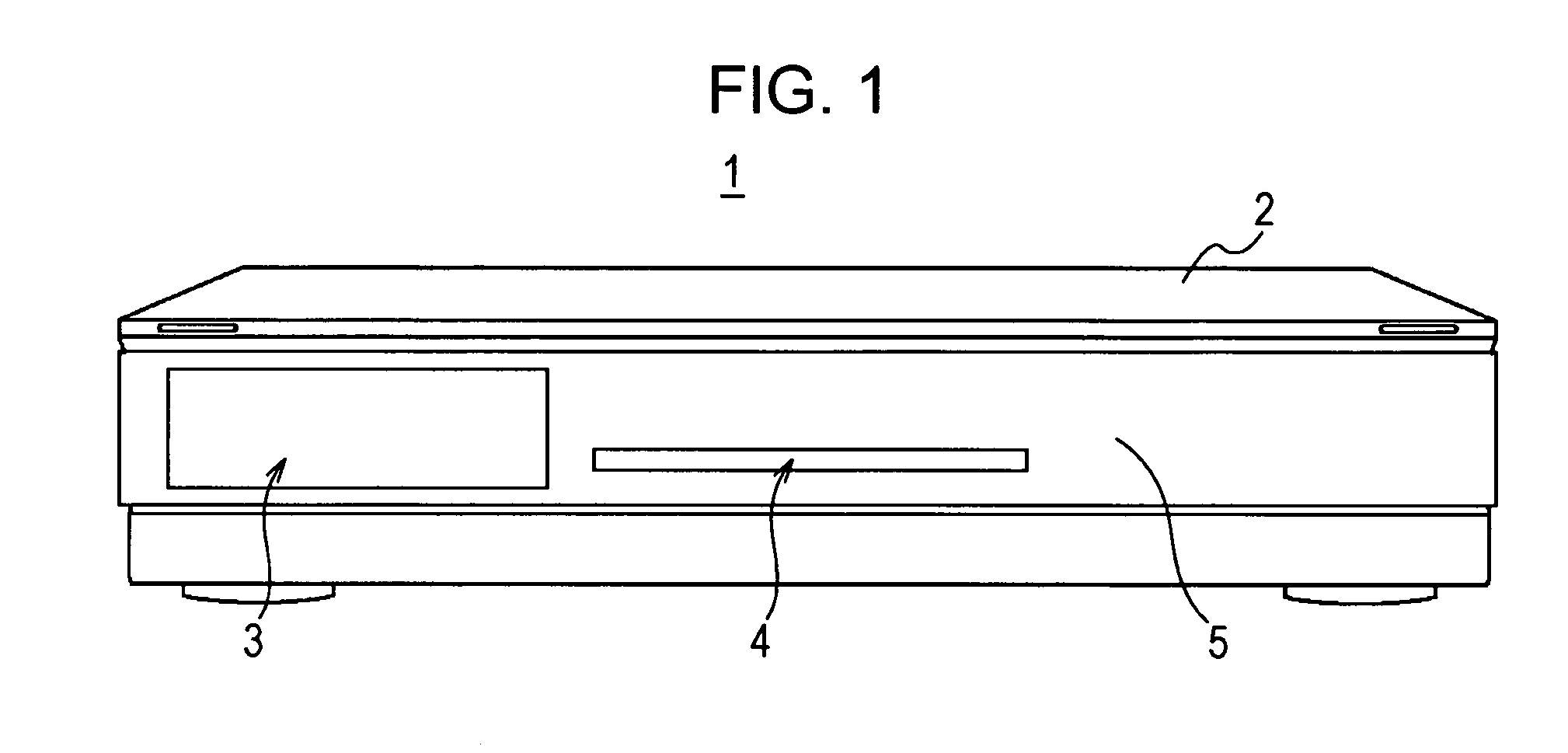
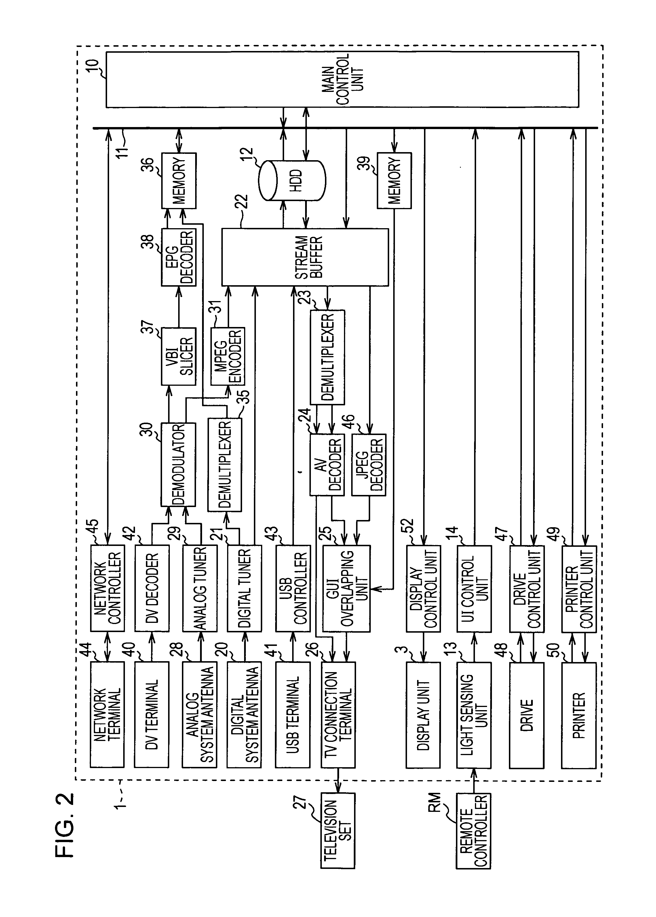
[0619]In the aforementioned embodiment, a case has been described where the program recording device 1 is configured to generate the print image and print it on one surface of the disc when the recording disc where the contents data are recorded is installed, and the print mode is selected.

[0620]However, the present invention is not limited thereto, but the program recording device 1 may be configured such that, when an unused (new) recording disc is installed, and the recording of the contents data is terminated, the characteristic depiction image is continuously cut out from the representative image representing the corresponding contents data, and the characteristic depiction image is printed on one surface of the disc as the print image.

modification 2

2-2. Modification 2

[0621]In the aforementioned embodiment, a case has been described where a circular print image is generated by bonding one end and the other end of a single direction, where the image characteristic portion is longitudinally depicted, of the characteristic depiction image cut out from the representative image.

[0622]However, the present invention is not limited thereto, but may be configured such that, as shown in FIG. 38, in the characteristic depiction image 110 cut out from the representative image, pixels are interpolated in an one end portion 110A of the other direction perpendicular to a single direction where the image characteristic portion is longitudinally depicted in order to enlarge the width of the other direction.

[0623]The present invention may be configured such that, in the characteristic image 111 obtained by enlarging the width of the other direction, a circular print image may be generated by collectively setting one end of an end portion 111A ob...

modification 3

2-3. Modification 3

[0628]Furthermore, in the aforementioned embodiment, a case has been described where the representative image is analyzed based on the values of R, G, and B of the pixels to detect the characteristic depiction area, and the characteristic depiction area is cut out as the characteristic depiction image from the representative image.

[0629]However, the present invention is not limited thereto, but may be configured such that the representative image is analyzed based on the color, chroma, brightness (HSV: Hue Saturation value), luminance, or the like to detect the characteristic depiction area, and the characteristic depiction area is cut out as the characteristic depiction image from the corresponding representative image.


PUM


Abstract

A print apparatus includes: a print image generation unit that generates a circular print image by bonding one end and the other end of a single direction of a representative image where an image characteristic portion extending in a single direction is depicted to represent contents recorded on the recording disc; and a print unit that prints the print image on one surface of the recording disc by matching a center of the recording disc with a center of the print image.

Description

BACKGROUND OF THE INVENTION[0001]1. Field of the Invention[0002]The present invention relates to a print apparatus, a print method, and a print program. For example, the present invention is very suitable for a program recording device capable of recording a television broadcasting program.[0003]2. Description of the Related Art[0004]A print apparatus of the related art determines a characteristic portion (hereinafter, also referred to as an image characteristic portion) within a rectangular image (hereinafter, also referred to as a recording image) recorded on a disc such as a CD (Compact Disc) or a DVD (Digital Versatile Disc). In addition, the print apparatus also determines a center position of the image characteristic portion for that recording image.[0005]The print apparatus determines, as a printable area, an area between the first concentric circle having the smallest radius and the third concentric circle having the largest radius among first to third concentric circles hav...

Claims


Application Information

Patent Timeline
IPC IPC(8): B41F17/00B41F33/00
CPCG11B23/40B41P2217/55
Inventor KANEKIYO, YUKIKOSUITO, TAROTAKESHIMA, KURIKO
Owner SONY CORP
Learn More