
Silicone free Anti-foaming process and controlled foaming process for petroleum coking

a petroleum coking and anti-foaming technology, applied in the direction of thermal non-catalytic cracking, separation processes, liquid degasification, etc., can solve the problems of undesirable coke material and reduce the production of valuable liquids, and achieve the effect of reducing the foam heigh

Active Publication Date: 2010-12-02
UNIVERSITY OF TULSA
View PDF18 Cites 10 Cited by
  • Summary
  • Abstract
  • Description
  • Claims
  • Application Information

AI Technical Summary

Benefits of technology

[0005]In one embodiment, the current invention provides a method for precluding foam-over during a petroleum coking operations. The method of the current invention comprises the steps of initiating the fill cycle of the coking process by filling a coke drum with a coke feedstock. During the fill cycle, feedstock level within the drum is monitored. Feedstock flow to the drum stops when the drum has filled to about 66% to about 80% of the internal volume of coke drum. To preclude foam-over into an overhead line associated with the coke drum, sufficient volume of non-silicone anti-foam agent is injected into the coke drum to control or preclude the formation of foam within said coke drum. Subsequently the method injects a sufficient volume of non-silicone anti-foam agent into the drum to kill the foam layer and initiate the coke induction period.
[0006]In another embodiment, the current invention provides a method for controlling the foam layer in a coke drum during the fill cycle of a coking process. As the coke drum is filled with feedstock, the resulting growth of a foam layer is monitored. Either when the foam layer reaches a predetermined height above the fluid feedstock or when foam is initially detected, cyc

Problems solved by technology

Operators must control foaming within the coke drums otherwise the foam will enter the overhead vapor line resulting in a blockage.
Thus, operations which use too little silicone based AF agent may foam-over and carry the silicone downstream.
However, excessive usage of silicone based AF agent, due to continuous injection, increases costs, may reduce the production of valuable liquids and may lead to an undesirable coke material.

Method used


Image

  • Silicone free Anti-foaming process and controlled foaming process for petroleum coking

Examples


Embodiment Construction

[0009]Feedstocks to all cokers vary from time to time. Therefore, one skilled in the art is accustomed to adjusting injection rates, times and quantities of AF agent to account for the variables of each feedstock. Since delayed coking is by far the most common coking method used today, the current invention will be described in the scope of a delayed coking process. However, those skilled in the art will recognize that the following non-silicone anti-foaming methods are equally applicable to fluid and flexi coking methods.

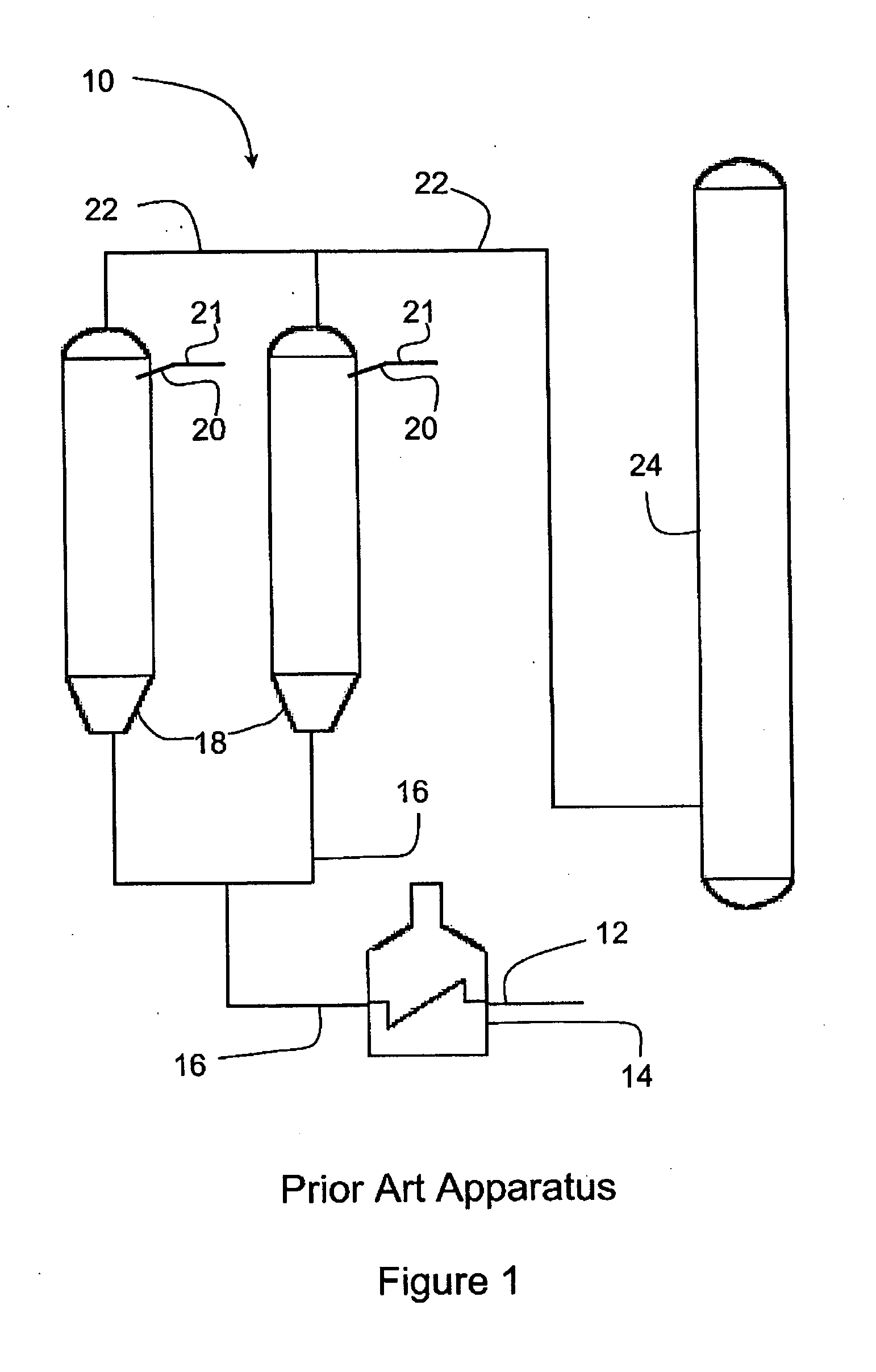
[0010]A typical coking operation uses two coking drums. Each drum cycles through eight standard steps:[0011]1. Drum fill / coke conversion—Feedstock enters a preheated drum, which begins to fill with coke. (The time required to fill the drum to the desired level is referred to herein as the fill cycle, fill step or fill time.) Once a drum is full, feedstock is directed to an empty drum and the full drum is brought off-line.[0012]2. Steamout—Steam stripping to help st...


PUM

PropertyMeasurementUnit
Fractionaaaaaaaaaa
Fractionaaaaaaaaaa
Fractionaaaaaaaaaa

Abstract

The current invention provides an improved petroleum coking process wherein the risk of silicone poisoning of units downstream of the coke drums is eliminated. The method of the current invention controls the foam layer within the coke drum by injection of a non-silicone anti-foam agent, preferably a tire oil. In another embodiment, the current invention provides a controlled foaming method which increases the liquid production from the coke drum. In the controlled foaming method, an anti-foam agent is cyclically injected into the drum early in the coke drum fill cycle. The cyclic injections manage the foam layer without inducing the induction phase in the coke feedstock, thereby increasing the total volume of feedstock received by the coke drum.

Description

BACKGROUND OF THE INVENTION[0001]A modern petroleum refinery is designed to maximize the production of select liquid products from crude oil. In addition to the well known atmospheric and vacuum distillation processes used to provide refined products, many refineries utilize petroleum cokers to further process the residual materials remaining after distillation. The three common coking processes, fluid, flexi and delayed coking, have been used for decades. As such the common operating conditions for petroleum coking are well known throughout the industry.[0002]During the fill cycle of the coking process, a foam layer forms on the surface of the feedstock as it fills the coke drum. Operators must control foaming within the coke drums otherwise the foam will enter the overhead vapor line resulting in a blockage. The preferred method for precluding foam-over, requires injecting a silicone based anti-foam agent (AF agent or material) into the drum. According to a tutorial presented by G...

Claims


Application Information

Patent Timeline
IPC IPC(8): C10G1/06
CPCB01D19/0404C10B55/00C10G9/005C10G2300/80C10G2300/1077C10G2300/70C10G2300/705C10G2300/1033
Inventor VOLK, JR., MICHAEL
Owner UNIVERSITY OF TULSA
Learn More