Three-stable oscillating electromagnetic actuator

Inactive Publication Date: 2010-12-02
MITSUBISHI ELECTRIC CORP
7 Cites 4 Cited by

AI-Extracted Technical Summary

Problems solved by technology

However, because a path of a magnetic flux is mainly in a radial direction, the degree of contrib...

Method used

[0091]As described above, a magnetic flux that passes through the mover 1 in the tangent direction becomes a rotation driving force, and a magnetic flux that passes through the mover 1 in the radial direction does not become the rotation driving force. Therefore, the electromagnetic actuator 101 according to the present embodiment is provided with the stoppers 21a and 21b forming the second magnetic poles that abut against the rotation-direction ends of the mover 1 in the first stable position and the second stable position and stop the mover 1. The engaging convex portions 1b and 1b are provided on both ends of the mover 1 in the rotation direction. With this arrangement, as shown in FIGS. 5 to 8, at the later stage of the driving operation, less magnetic flux flows in the radial direction, and more magnetic flux flows in the tangent direction, and a large rate of magnetic flux can contribute to the rotation driving force, and a high torque can be obtained. By efficiently converting a magnetic flux into a torque, the electromagnetic actuator 101 can reduce the size and power consumption thereof.
[0102]As described above, in the actuator 105 according to the present embodiment, the second coils 47G and 47H respectively arranged in the first stable position and the second stable position to surround the mover 1 are provided in the first stable position and the second stable position, respectively. All ...

Benefits of technology

[0012]According to the present invention, the actuator has a second magnetic pole that is made of a magnetic material and operates as a magnetic pole, that abuts against a rotation-direction end of a mover to stop ...

Abstract

A three-stable oscillating electromagnetic actuator includes a cylindrical stator from which a plurality of first magnetic poles project toward a center direction, a mover that extends in a circumferential direction inside the stator and is reciprocatingly and rotatably supported along the circumference, and a plurality of coils that are wound around the first magnetic poles and bias the mover to cause it to stop in three positions, which are a first stable position that is on one end side of a rotation range of the mover, a second stable position that is on the other end side, and a neutral position that is an intermediate position. The three-stable oscillating electromagnetic actuator further includes a second magnetic pole made of a magnetic material that abuts against a rotation-direction end of the mover to stop the mover in the first stable position and the second stable position.

Application Domain

Technology Topic

Image

  • Three-stable oscillating electromagnetic actuator
  • Three-stable oscillating electromagnetic actuator
  • Three-stable oscillating electromagnetic actuator

Examples

  • Experimental program(14)

Example

First Embodiment
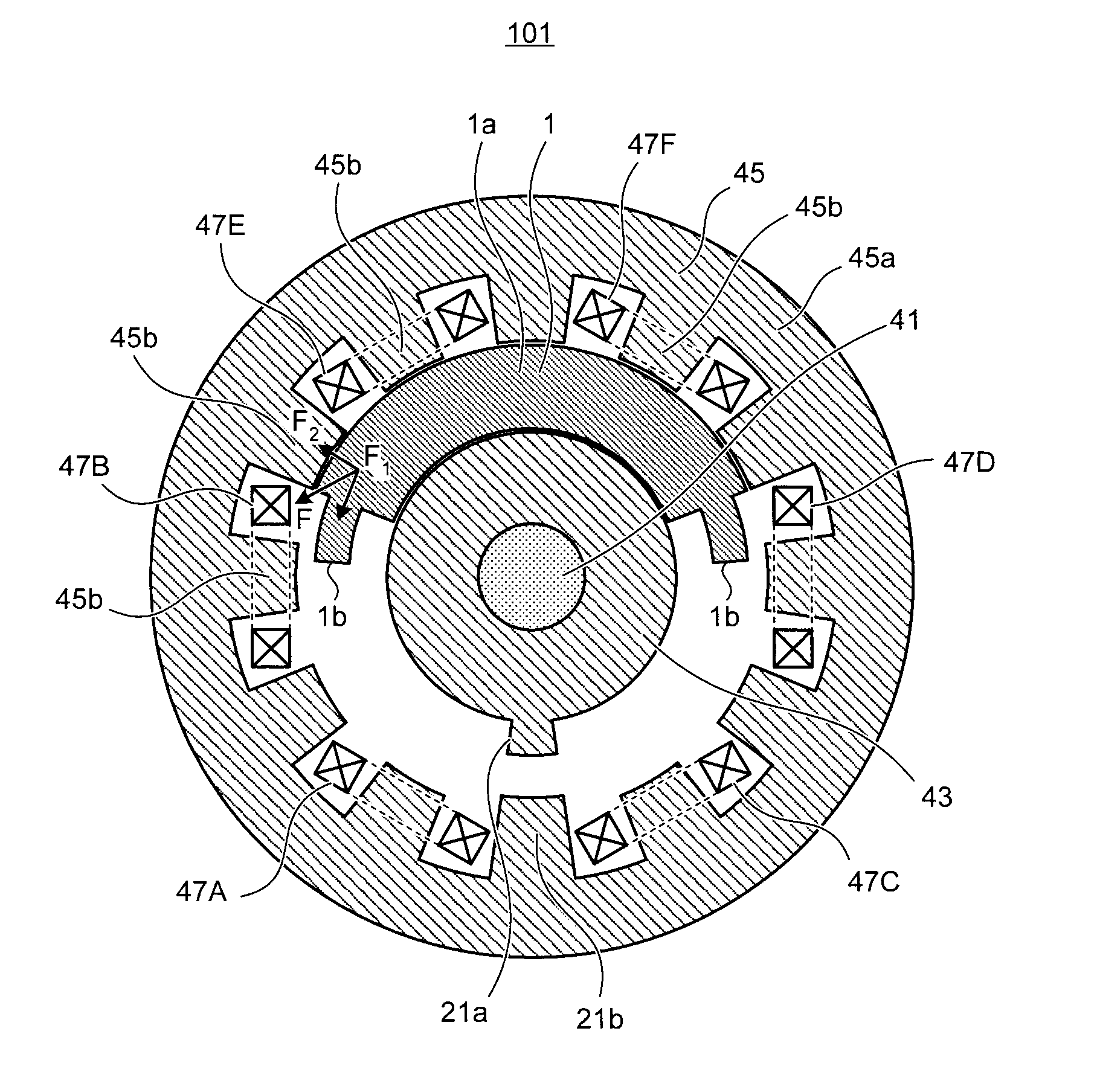
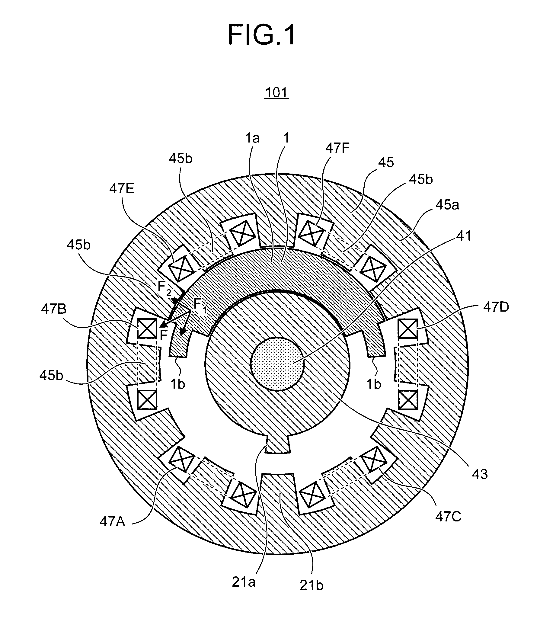
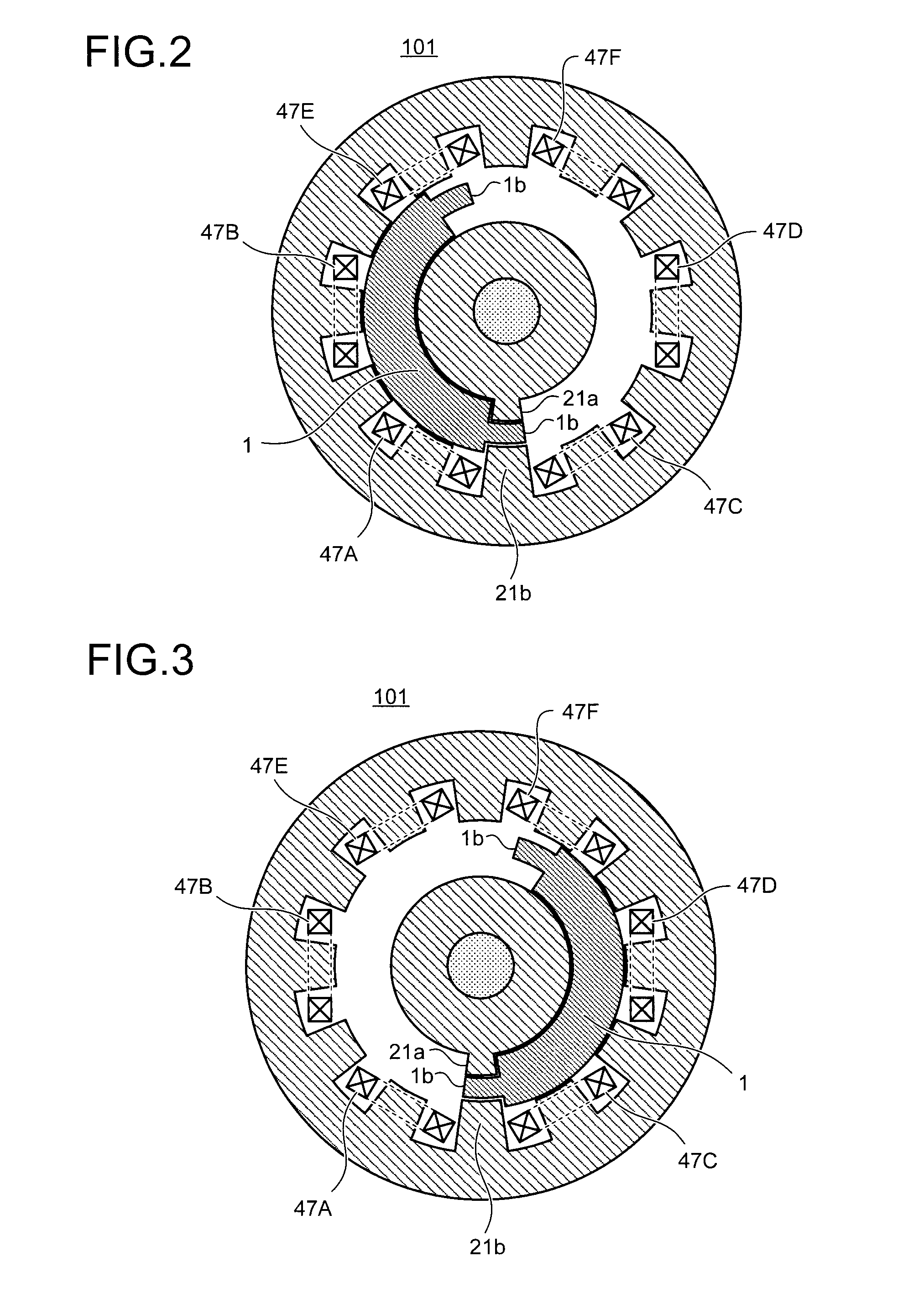
[0080]FIG. 1 is a cross-sectional view of a three-stable oscillating electromagnetic actuator according to a first embodiment of the present invention, and depicts a state where a mover is in a neutral position. FIG. 2 is a cross-sectional view of a state where the mover is in a first stable position. FIG. 3 is a cross-sectional view of a state where the mover is in a second stable position. As shown in FIG. 1, a three-stable oscillating electromagnetic actuator 101 includes a center member 43 provided around a rotation shaft 41; a stator 45 coaxially provided around the center member 43 at a predetermined distance and from which plural teeth (first magnetic poles) 45b project toward a center direction; and a mover 1 that is arranged in a cylindrical space formed between the center member 43 and the stator 45, extends in a circumferential direction, and is supported to be capable of reciprocatingly rotating in the circumferential direction. The three-stable oscillating electromagnetic actuator 101 also includes a plurality of coils 47A, 47B, 47C, 47D, 47E, and 47F that are wound around the first magnetic poles 45b and bias the mover 1 to three positions, i.e., a first stable position, a second stable position, and a neutral position; and stoppers 21a and 21b that abut against rotation-direction ends of the mover 1 in the first stable position and the second stable position to stop the mover 1 and form second magnetic poles made of a magnetic material.
[0081]The center member 43 is made of a magnetic material, and is formed in a substantially short cylindrical shape. A projection 21a forming one of the second magnetic poles is formed at a predetermined position on an outer peripheral surface of the center member 43. The stator 45 is made of a magnetic material and arranged to surround the center member 43. The stator 45 includes a substantially short cylindrical yoke 45a, and the plural teeth (first magnetic poles) projecting from an inner periphery of the yoke 45a toward a center direction. A projection 21b forming the other second magnetic pole is formed at a position opposed to the projection 21a provided on the center member 43.
[0082]Left-rotation coils 47A and 47B, right-rotation coils 47C and 47D, and neutral-position-stable coils 47E and 47F are wound around the plural first magnetic poles 45b formed on the stator 45 along a circumference thereof at equal distances from one another.
[0083]The mover 1 has substantially an arc cross section, extends along the circumferential direction, and is supported by a support member (not shown) such that the mover 1 can rotate from a rotation center, and rotates in a reciprocating manner between the first stable position and the second stable position. The mover 1 includes a main unit 1a having an arc cross section, and engaging convex portions 1b and 1b formed on both ends of the main unit 1a in its rotation direction. The engaging convex portions 1b and 1b are formed at locations shifted from a center of the end of the main unit 1a in its radial direction by a predetermined amount toward the coil (towards an outer diameter side). The engaging convex portions 1b and 1b have such shapes that the engaging convex portions 1b and 1b are fitted into a gap formed between the stoppers (second magnetic poles) 21a and 21b. That is, the gap formed between the stoppers 21a and 21b forms the engaging concave portion that engages with the engaging convex portions 1b and 1b. When the mover 1 moves to the first stable position or the second stable position, one of the engaging convex portions 1b is inserted into the gap formed between the stoppers 21a and 21b, the end of the mover 1 is abutted against the stoppers 21a and 21b and movement of the mover 1 is limited.
[0084]An operation is described. When the mover 1 is driven from the neutral position shown in FIG. 1 to the first stable position shown in FIG. 2, a magnetic flux is formed between the mover 1 and the stator 45 if a current is applied to the coils 47A and 47B. The mover 1 is driven in a counterclockwise direction around the rotation shaft 41 as a rotation center. When the mover 1 reaches the first stable position shown in FIG. 2, the current application to the coils 47A and 47B is stopped.
[0085]When the mover 1 is driven from the first stable position shown in FIG. 2 to the neutral position shown in FIG. 1, a magnetic flux is formed between the mover 1 and the stator 45 if a current is applied to the coils 47E and 47F, and the mover 1 is driven in a clockwise direction around the rotation shaft 41 as a rotation center. When the mover 1 reaches the neutral position shown in FIG. 1, the current application to the coils 47E and 47F is stopped.
[0086]Because the structure is bilaterally symmetric, explanations of other operations are omitted; however, by switching the coils to which a current is applied as described above, the mover 1 can reciprocate between the neutral position shown in FIG. 1, the first stable position shown in FIG. 2, and the second stable position shown in FIG. 3.
[0087]When the mover 1 is driven from the neutral position shown in FIG. 1 to the first stable position shown in FIG. 2, the mover 1 is attracted by the coil 47B at an initial stage of a driving operation and the mover 1 is attracted by the coil 47A at a later stage of the driving operation. Other operations are also the same. By attracting the mover 1 while switching between the coils to which a current is applied in this manner, a strong electromagnetic force can be generated even when a moving distance is long.
[0088]Next, a load curve of a contact of a switch (not shown) connected to the three-stable oscillating electromagnetic actuator 101 is shown in FIG. 4. When the mover 1 is driven from the neutral position shown in FIG. 1 to the first stable position shown in FIG. 2, the load is small at the initial stage of the driving operation and the load becomes large at the later stage of the driving operation. When the mover 1 is driven from the first stable position shown in FIG. 2 to the neutral position shown in FIG. 1, the load is large at the initial stage of the driving operation and the load becomes small at the later stage of the driving operation. The same phenomenon appears also when the mover 1 is driven to the second stable position shown in FIG. 3.
[0089]In the electromagnetic actuator 101 of the present embodiment, the coils 47A, 47B, 47C, 47D, 47E, and 47F are arranged on the circumference of the stator 45. Therefore, magnetic fluxes generated from the coil pass through the mover 1 and flow in a radial direction (an arrow F2 in FIG. 1) and a tangent direction (an arrow F1 in FIG. 1). A force in the tangent direction is required when obtaining a rotation driving force of the mover 1. A magnetic flux that passes through the mover 1 in the tangent direction contributes as a rotation driving force; however, a magnetic flux that passes through the mover 1 in the radial direction does not contribute to the rotation driving force. Thus, the electromagnetic actuator 101 according to the present embodiment is provided with the stoppers 21a and 21b forming the second magnetic poles that abut against the rotation-direction ends of the mover 1 in the first stable position and the second stable position and stop the mover 1. The engaging convex portions 1b and 1b are provided on both ends of the mover 1 in the rotation direction.
[0090]FIG. 5 is a cross-sectional view of a state where magnetic fluxes are generated at the initial stage of the driving operation from the neutral position to the first stable position. More magnetic fluxes generated on one side of the coil 47B are applied in the tangent direction due to effect of the engaging convex portion 1b of the mover 1. FIG. 6 is a cross-sectional view of a state where magnetic fluxes are generated at the later stage of the driving operation from the neutral position to the first stable position. More magnetic fluxes generated on one side of the coil 47A provided in the first stable position are applied in the tangent direction due to effect of the stoppers (second magnetic poles) 21a and 21b and the engaging convex portion 1b. FIG. 7 is a cross-sectional view of a state where magnetic fluxes are generated at the initial stage of the driving operation from the first stable position to the neutral position. More magnetic fluxes generated on one side of the coil 47E are applied in the tangent direction due to effect of the engaging convex portion 1b. FIG. 8 is a cross-sectional view of a state where magnetic fluxes are generated at the later stage of the driving operation from the first stable position to the neutral position. More magnetic fluxes generated on the coils 47E and 47F are applied in the tangent direction like in a conventional technique.
[0091]As described above, a magnetic flux that passes through the mover 1 in the tangent direction becomes a rotation driving force, and a magnetic flux that passes through the mover 1 in the radial direction does not become the rotation driving force. Therefore, the electromagnetic actuator 101 according to the present embodiment is provided with the stoppers 21a and 21b forming the second magnetic poles that abut against the rotation-direction ends of the mover 1 in the first stable position and the second stable position and stop the mover 1. The engaging convex portions 1b and 1b are provided on both ends of the mover 1 in the rotation direction. With this arrangement, as shown in FIGS. 5 to 8, at the later stage of the driving operation, less magnetic flux flows in the radial direction, and more magnetic flux flows in the tangent direction, and a large rate of magnetic flux can contribute to the rotation driving force, and a high torque can be obtained. By efficiently converting a magnetic flux into a torque, the electromagnetic actuator 101 can reduce the size and power consumption thereof.

Example

Second Embodiment
[0092]FIG. 9 is a cross-sectional view of a three-stable oscillating electromagnetic actuator according to a second embodiment of the present invention, and is a cross-sectional view of a state where magnetic fluxes are generated at an initial stage of a driving operation from a neutral position to a first stable position. As shown FIG. 9, in a three-stable oscillating electromagnetic actuator 102 according to the present embodiment, a mover 2 is not provided at its end with an engaging convex portion. Corresponding to this configuration, a stopper made of a magnetic material that operates as a second magnetic pole is continuously formed from the center member 43 to the stator 45 without interruption. Other configurations of the second embodiment are the same as those of the first embodiment.
[0093]FIG. 10 is a cross-sectional view of a state where magnetic fluxes are generated at a later stage of the driving operation from the neutral position to the first stable position. FIG. 11 is a cross-sectional view of a state where magnetic fluxes are generated at the initial stage of the driving operation from the first stable position to the neutral position. FIG. 12 is a cross-sectional view of a state where magnetic fluxes are generated at the later stage of the driving operation from the first stable position to the neutral position. In FIG. 9, because a gap between the mover 2 and a magnetic pole of the coil 47B is large at the initial stage of the driving operation from the neutral position to the first stable position, an electromagnetic force generated in the coil 47B is small.
[0094]In FIG. 10, because an end surface of the mover 2 in a rotation direction and a stopper (a second magnetic pole) 22 abut against each other at the later stage of the driving operation from the neutral position to the first stable position, a generated electromagnetic force is large. In FIGS. 11 and 12, in the driving operation from the first stable position to the neutral position, the position of the magnetic pole is the same as that in the first embodiment at both the initial stage and the later stage, and thus the same electromagnetic force is obtained.

Example

Third Embodiment
[0095]FIG. 13 is a cross-sectional view of a state of a three-stable oscillating electromagnetic actuator according to a third embodiment of the present invention, and is a cross-sectional view of a state where magnetic fluxes are generated at a initial stage of a driving operation from a neutral position to a first stable position. As shown in FIG. 13, in a three-stable oscillating electromagnetic actuator 103 according to the present embodiment, a mover 3 includes a main unit 3a having an arc cross section, and engaging convex portions 3b and 3b formed on both ends of the main unit 3a in a rotation direction. The engaging convex portions 3b and 3b project from innermost-diameter sides of the ends of the main unit 3a. Corresponding to this configuration, a stopper 23 made of a magnetic material that operates as a second magnetic pole is formed as a projection upright from the stator 45 toward a center member 43. Other configurations of the third embodiment are the same as those of the first embodiment.
[0096]FIG. 14 is a cross-sectional view of a state where magnetic fluxes are generated at a later stage of the driving operation from the neutral position to the first stable position. FIG. 15 is a cross-sectional view of a state where magnetic fluxes are generated at the initial stage of the driving operation from the first stable position to the neutral position. FIG. 16 is a cross-sectional view of a state where magnetic fluxes are generated at the later stage of the driving operation from the first stable position to the neutral position. In FIG. 13, at the initial stage of the driving operation from the neutral position to the first stable position, because the engaging convex portion 3b that operates as the magnetic pole projects, more magnetic fluxes pass through the mover 3 as compared with the second embodiment, and the generated electromagnetic force is increased. In FIG. 14, at the later stage of the driving operation from the neutral position to the first stable position, because an end surface of the engaging convex portion 3b of the mover 3 does not abut against the stopper 23 forming the magnetic pole, an electromagnetic force to be generated is reduced as compared with that of the second embodiment. In FIGS. 15 and 16, in the driving operation from the first stable position to the neutral position, the engaging convex portions 3b and 3b formed at the innermost-diameter sides of the ends of the main unit 3a do not influence almost at all, there is no large difference between the generated electromagnetic force in the third embodiment and that in the second embodiment.

PUM

no PUM

Description & Claims & Application Information

We can also present the details of the Description, Claims and Application information to help users get a comprehensive understanding of the technical details of the patent, such as background art, summary of invention, brief description of drawings, description of embodiments, and other original content. On the other hand, users can also determine the specific scope of protection of the technology through the list of claims; as well as understand the changes in the life cycle of the technology with the presentation of the patent timeline. Login to view more.

Similar technology patents

Servo control chip SIP system special for chip atomic clock, test device and method

PendingCN114428473AReduce size and power consumptionShrink chip line widthProgramme controlApparatus using atomic clocksEmbedded systemErbium lasers
Owner:BEIJING INST OF RADIO METROLOGY & MEASUREMENT

Signal detection device and system

InactiveCN110058314AReduce size and power consumptionConducive to multi-channel distributed detectionElectric/magnetic detectionAcoustic wave reradiationVoltageSignal production
Owner:INST OF MICROELECTRONICS CHINESE ACAD OF SCI

Large-area-array and high-frame-rate image collection device

ActiveCN107948467AIncrease output frame rateReduce size and power consumptionTelevision system detailsColor television detailsImage storageDigital video
Owner:西安应用光学研究所

Self-driven ignition device without external power supply and preparing method of self-driven ignition device

ActiveCN105466291AReduce size and power consumptionBlastingElectric fieldExternal energy
Owner:BEIJING INSTITUTE OF TECHNOLOGYGY

Classification and recommendation of technical efficacy words

  • Reduce size and power consumption

Combined navigation system and method

InactiveCN102654582AImprove continuous positioning abilityReduce size and power consumptionSatellite radio beaconingWeight UnitAir navigation
Owner:TECHTOTOP MICROELECTRONICS

Synchronization detecting circuit and multimode wireless communication apparatus

ActiveUS20090103516A1Reduce size and power consumptionEnergy efficient ICTSynchronisation arrangementWirelessSynchronous detection
Owner:PANASONIC CORP

Integrated attitude measurement system for microsatellite

InactiveCN108072372AReduce size and power consumptionImprove efficiencyInstruments for comonautical navigationThree axis accelerometerAttitude control
Owner:NORTHWESTERN POLYTECHNICAL UNIV

Humidifier for proton exchange membrane fuel cell

ActiveCN102956908AReduce size and power consumptionMake up for resistanceFuel cell auxillariesExhaust gasEngineering
Owner:BEIJING SHOTO ENERGY STORAGE TECH CO LTD
Why Eureka
Try Eureka