

Signal detection device and system
A signal detection and driving signal technology, applied in the field of signal detection, can solve the problems of large error of detection results and high power consumption, and achieve the effect of eliminating the influence of measurement results, reducing volume and power consumption, and reducing performance mismatch
- Summary
- Abstract
- Description
- Claims
- Application Information
AI Technical Summary
Problems solved by technology
Method used
Image

Examples
Embodiment 1
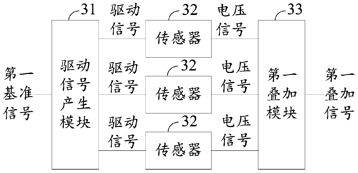
[0038] This embodiment provides a signal detection device, image 3 is a structural schematic diagram of the signal detection device. The signal detection device includes a driving signal generating module 31 , a first signal superimposing module 33 and N sensors 32 , where N is an integer not less than 2. In this embodiment, the signal detection device is a weak magnetic detection device. Since the magnetic field is a vector signal, its XYZ three-axis component needs to be detected and transmitted, so the value of N can be set to 3, and each sensor 32 can be Magnetoresistive effect sensor. It should be noted that the signal detection device provided in this embodiment can also detect other vector signals with components of more than two axes, as long as the sensor 32 needs to work under the driving signal.
[0039] Specifically, the driving signal generation module 31 is configured to generate N driving signals with the same amplitude and different frequencies according to ...
Embodiment 2
[0045] Based on the same inventive concept, this embodiment provides another signal detection device, Figure 4 is a structural schematic diagram of the signal detection device. and image 3 Compared with the signal detection device shown, the signal detection device of this embodiment further includes a frequency configuration module 41 .
[0046] The frequency configuration module 41 is configured to obtain the first reference signal according to the second reference signal, and the frequency of the first reference signal is adjustable. The frequency configuration module 41 may be a digital frequency synthesizer, or a function signal generator based on a single-chip microcomputer and a digital-to-analog converter. By setting the frequency configuration module 41, multiple signal detection devices can generate multiple first reference signals with different frequencies according to the same second reference signal when performing multi-channel detection. Further, the frequ...
Embodiment 3
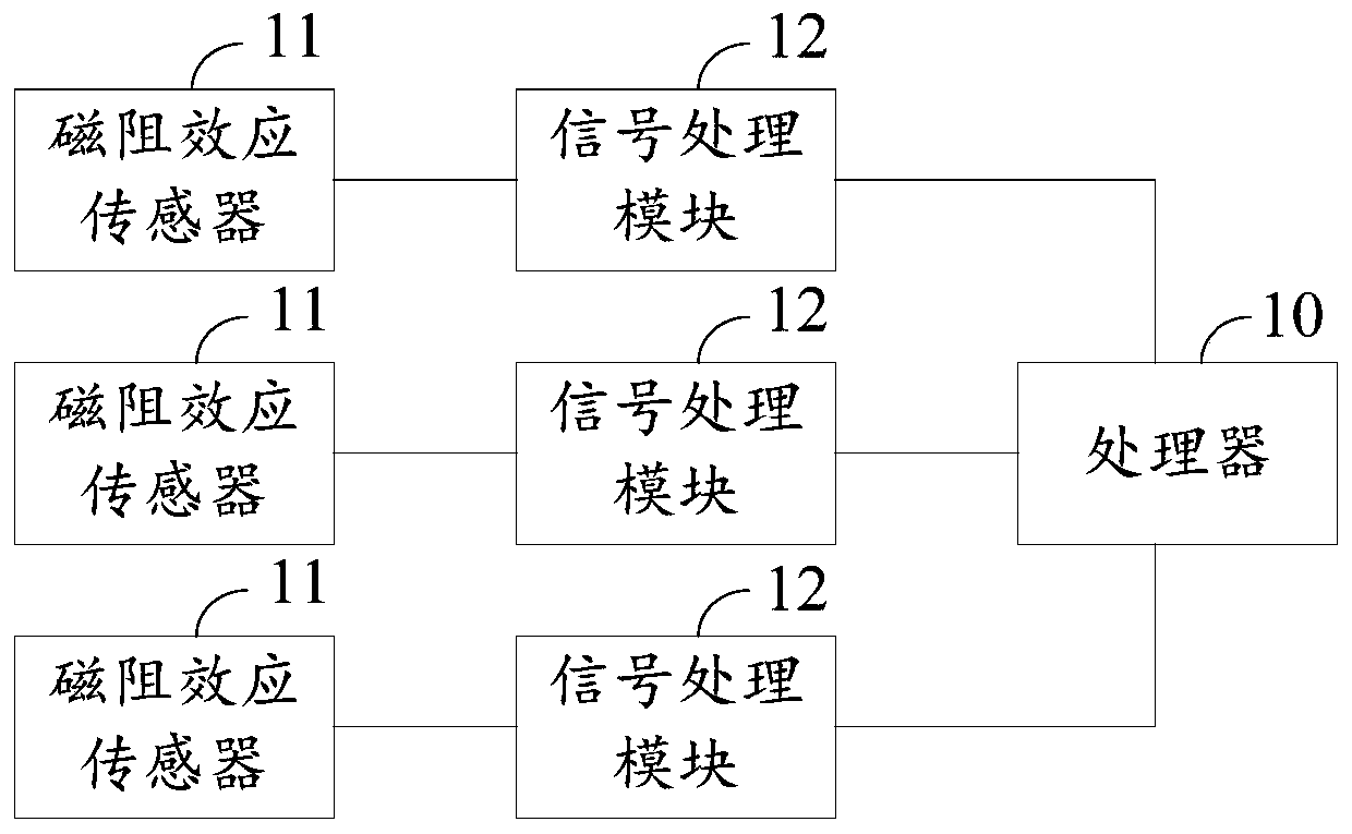
[0048] Based on the same inventive concept, this embodiment provides a signal detection system. Figure 5 is a structural schematic diagram of the signal detection system, the signal detection system includes a processor 50, M signal detection devices 51 and M signal processing modules 52, where M is an integer not less than 1.
[0049] The signal detection device 51 is the signal detection device provided in Embodiment 1 or Embodiment 2. Since each signal detection device 51 corresponds to a signal processing module 52, that is, each superimposed signal is processed separately, each signal detection device The frequencies of the first reference signals in 51 can be set to be equal. In this embodiment, description is made by taking the signal detection system including three signal detection devices as an example.
[0050] Each signal processing module 52 is configured to perform signal processing on the first superposition signal output by a signal detection device 51 to obt...
PUM
 Abstract
Description
Claims
Application Information