Self-driven ignition device without external power supply and preparing method of self-driven ignition device

An ignition device and external power supply technology, which is applied in the field of pyrotechnics, can solve problems such as poor reliability and complex drive circuits, and achieve the effect of reducing volume and power consumption

Active Publication Date: 2016-04-06
BEIJING INSTITUTE OF TECHNOLOGYGY
View PDF4 Cites 0 Cited by
  • Summary
  • Abstract
  • Description
  • Claims
  • Application Information

AI Technical Summary

Problems solved by technology

When this kind of pyrotechnic product works, it needs to rely on external energy input. It usually needs to be equipped with energy storage devices such as capacitors and batte

Method used


Image

  • Self-driven ignition device without external power supply and preparing method of self-driven ignition device
  • Self-driven ignition device without external power supply and preparing method of self-driven ignition device

Examples


Embodiment 1

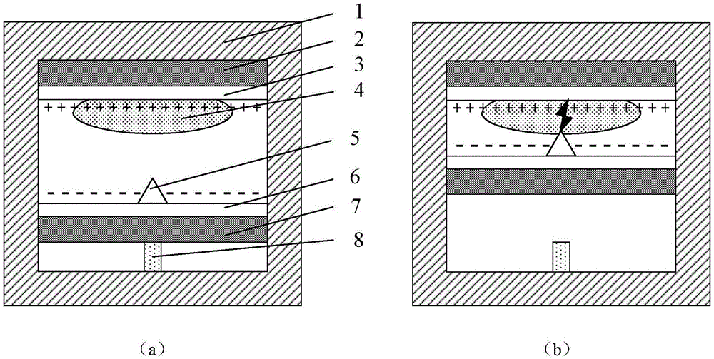
[0031] Such as figure 1 As shown, the self-driven ignition device of this embodiment without external power supply includes: ignition device housing 1, anode electret thin layer 2, anode conductive film 3, cathode electret thin layer 7, cathode conductive film 6, starting Pyrotechnic agent 4, ignition tip 5 and limiter 8; wherein, ignition device shell 1 adopts insulating material; A limiting device 8 is set between the electret cathode and the ignition device; the anode electret thin layer 2 and the cathode electret thin layer 7 face each other, are filled with positive and negative charges respectively, and the surfaces are respectively covered with the anode conductive film 3 and the cathode electret thin layer. The cathode conductive film 6; the anode conductive film 3 is opposite to the cathode conductive film 6, and the opposite surfaces of the two are respectively filled with positive charges and negative charges to form an electrostatic field; an initial pyrotechnic ag...

Embodiment 2

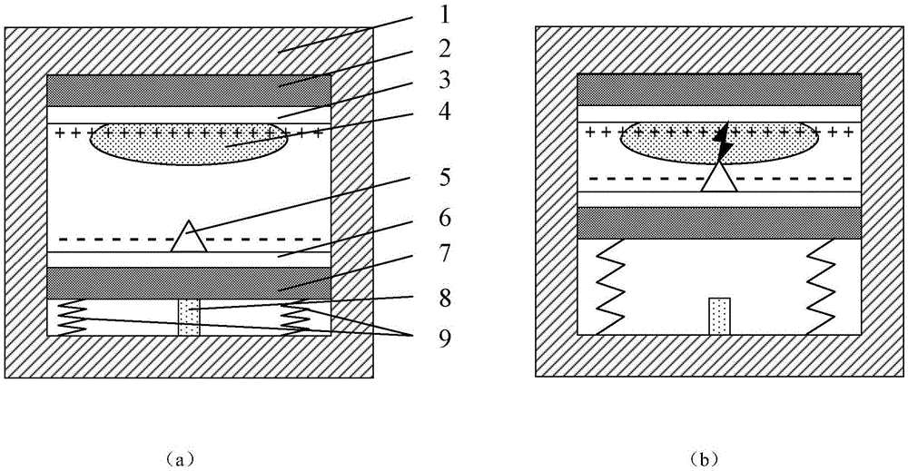
[0033] Such as figure 2 As shown, in this embodiment, a thrust providing device 9 is arranged between the electret cathode and the ignition device housing, the thrust providing device adopts a spring, and a plurality of springs are symmetrically arranged between the electret cathode and the ignition device housing, Others are the same as embodiment one. When the ignition device does not receive external force or the external force is less than the overload force threshold, limit the position of the electret cathode so that it cannot move, as shown in (a); when the axial force of the ignition device exceeds the overload force of the limit device When the threshold is reached, the limit device releases the electret cathode, and the electret cathode moves to the electret anode under the action of the electrostatic field, and the thrust provides transposition 9 to further provide external force to push the electret cathode to move to the electret anode, When the ignition tip of ...


PUM


Abstract

The invention discloses a self-driven ignition device without external power supply and a preparing method of the self-driven ignition device. Two opposite electret electrodes are adopted, one electret electrode is fixed, and the other electret electrode is limited in an ignition device shell through a limiting device. A positive charge and a negative charge are arranged on the opposite surfaces respectively, an electric field is formed, and an initiating fire work chemical and an ignition sharp end are arranged on the opposite surfaces respectively. When the stress of the ignition device in the axial direction exceeds the overload force threshold value of the limiting device, the limiting device releases the limited electret electrode, the electret electrode released is close to the other electret electrode, strong charge transferring is generated between the ignition sharp end and the other electret electrode, and spark discharge is formed. The initiating fire work chemical is ignited or detonated, and chemical output is achieved. By means of electrets with charges of different polarities, energy exchanging output without depending on external energy is achieved, the self-driven characteristic is achieved, and the size and the power consumption of initiating explosive device support devices can be obviously reduced.

Description

technical field [0001] The invention relates to pyrotechnics technology, in particular to a self-driven ignition device without external power supply and a preparation method thereof. Background technique [0002] Pyrotechnics are a type of transducing device used to convert external stimuli such as mechanical and electrical into heat or other forms of energy output. At present, most pyrotechnic products are electric pyrotechnic products, which are characterized by converting external electric energy into heat energy, or forming a form of high-temperature plasma energy output to burn the starting agent. This type of pyrotechnic device needs to rely on external energy input when it works, and usually needs to be equipped with energy storage devices such as capacitors and batteries, and also needs to be equipped with auxiliary devices such as control switch tubes, so the driving circuit is complicated and the reliability of the action is poor. Contents of the invention [0...

Claims


Application Information

Patent Timeline
IPC IPC(8): F42D1/045
CPCF42D1/045
Inventor 冯跃丁旭冉娄文忠
Owner BEIJING INSTITUTE OF TECHNOLOGYGY
Why Eureka
Try Eureka