Method and device for three-dimensional surface detection with a dynamic reference frame

hree-dimensional surface technology, applied in the field of three-dimensional surface detection with a dynamic reference frame, can solve the problems of inconvenient measurement, inability to achieve the acquisition of 3d topography from a single observation direction, and the sensor is not well-adapted, so as to achieve simple and robust acquisition of object surfaces.

Active Publication Date: 2010-12-02
DENTSPLY SIRONA INC
View PDF19 Cites 93 Cited by
  • Summary
  • Abstract
  • Description
  • Claims
  • Application Information

AI Technical Summary

Benefits of technology

[0017]It is accordingly an object of the invention to provide a method and device for 3D acquisition which overcome the above-mentioned disadvantages of the heretofore-known devices and metho

Problems solved by technology

During the time it takes the series of raw images, the object and the sensor have to stand still, which makes the sensor not well adapted, when relative motion between object and sensor is involved.
In many applications, the object has a complicated shape, so the acquisition of the 3D topography cannot be achieved from a single observation direction.
This procedure needs a stop and go movement of the sensor, which makes the measurement quite uncomfortable, even more so because only after the time consuming registration of the different views the user will know if there are parts of the object missing.
The achievable quality of the data and the technical costs however, make the sensor not yet competitive.
There exist other options to achieve a “single shot 3D sensor.” However, those sensors principally cannot deliver a complete set of 3D data.
The sensor uses only one-line laser triangulation, which makes it difficult to get complete and very accurate data.
The necessity to track the sensor makes a completely free motion difficult, because the tracking field of view must not be obscured by the person who moves th

Method used


Image

  • Method and device for three-dimensional surface detection with a dynamic reference frame
  • Method and device for three-dimensional surface detection with a dynamic reference frame
  • Method and device for three-dimensional surface detection with a dynamic reference frame

Examples


Embodiment Construction

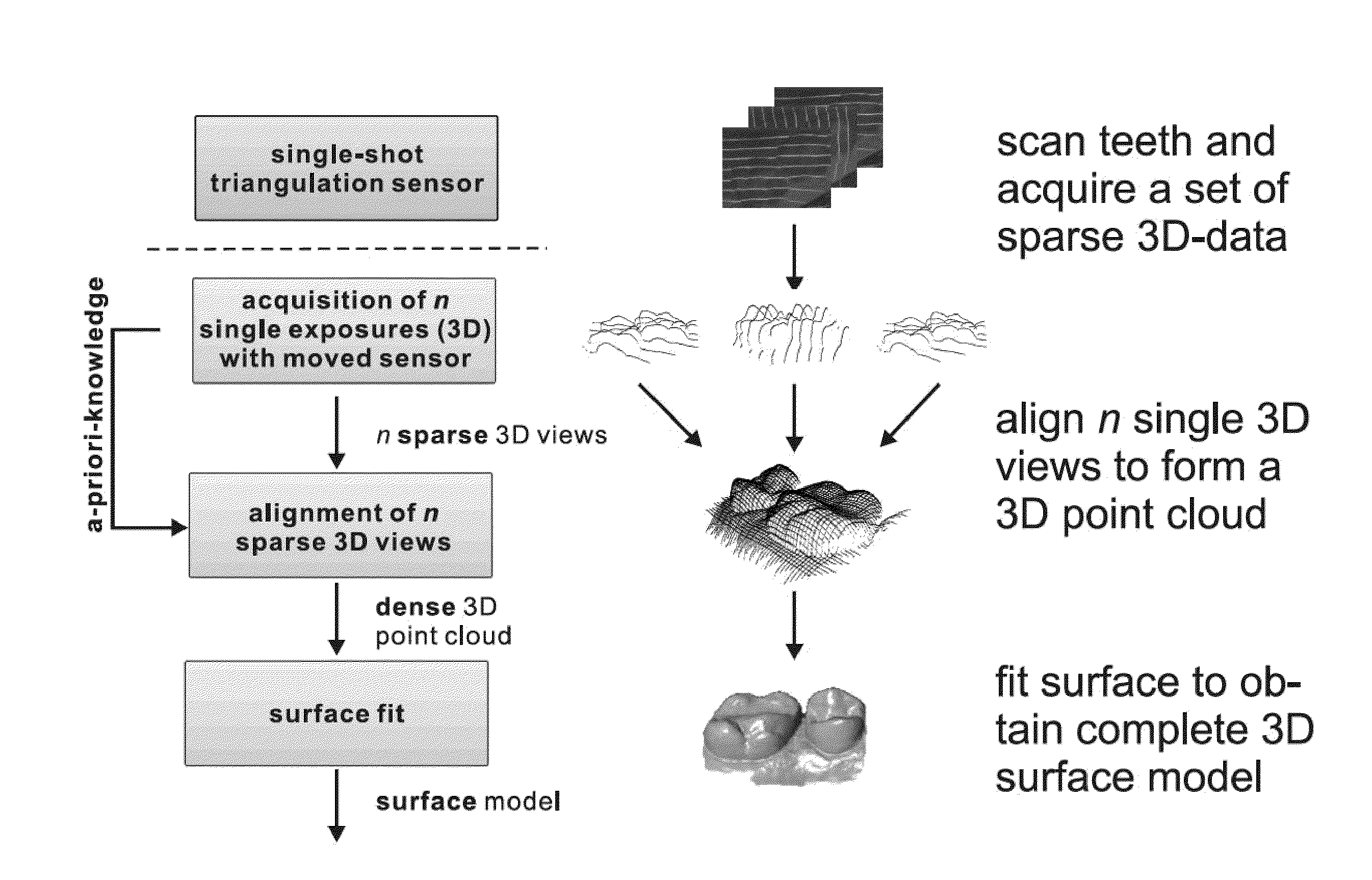
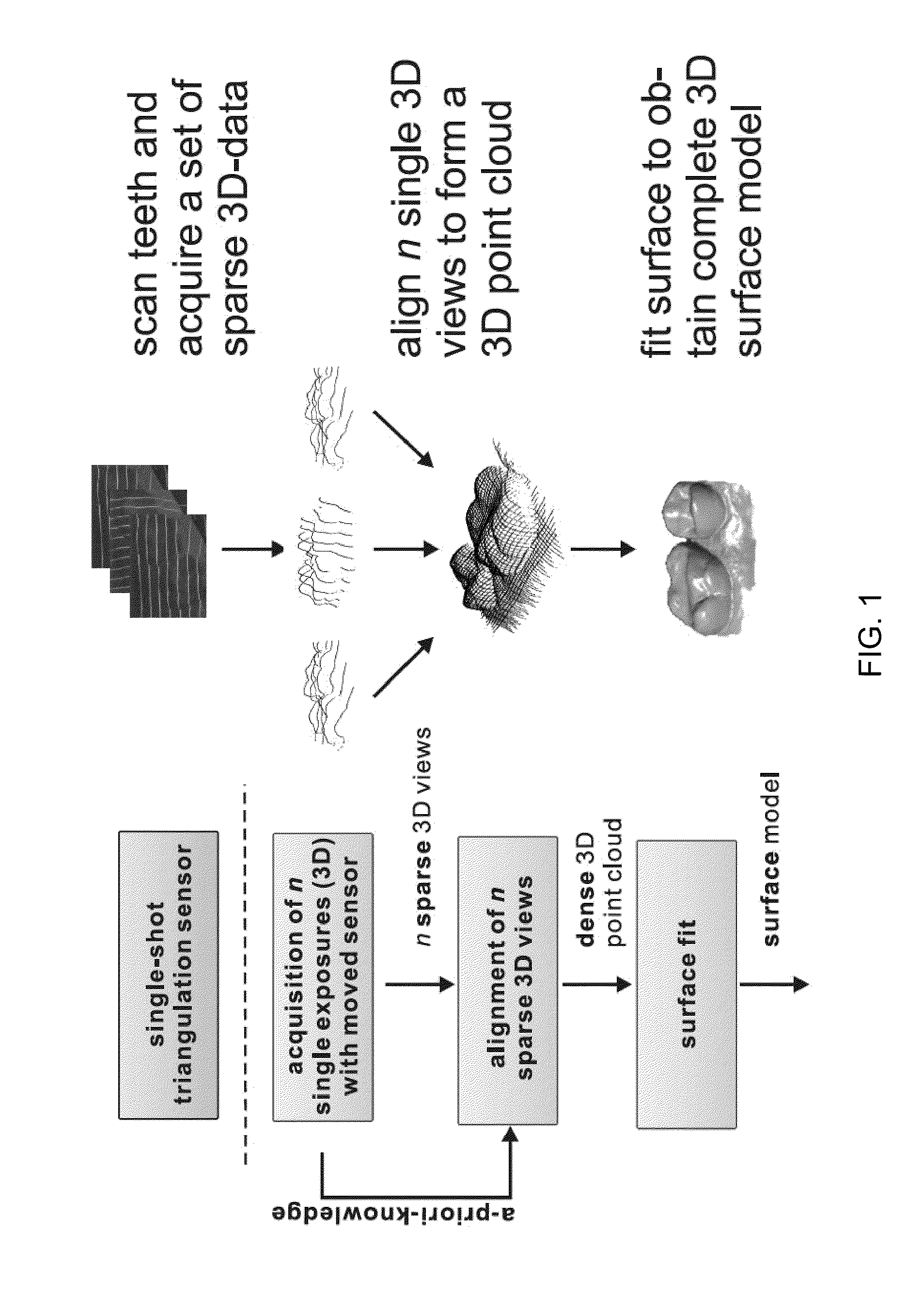
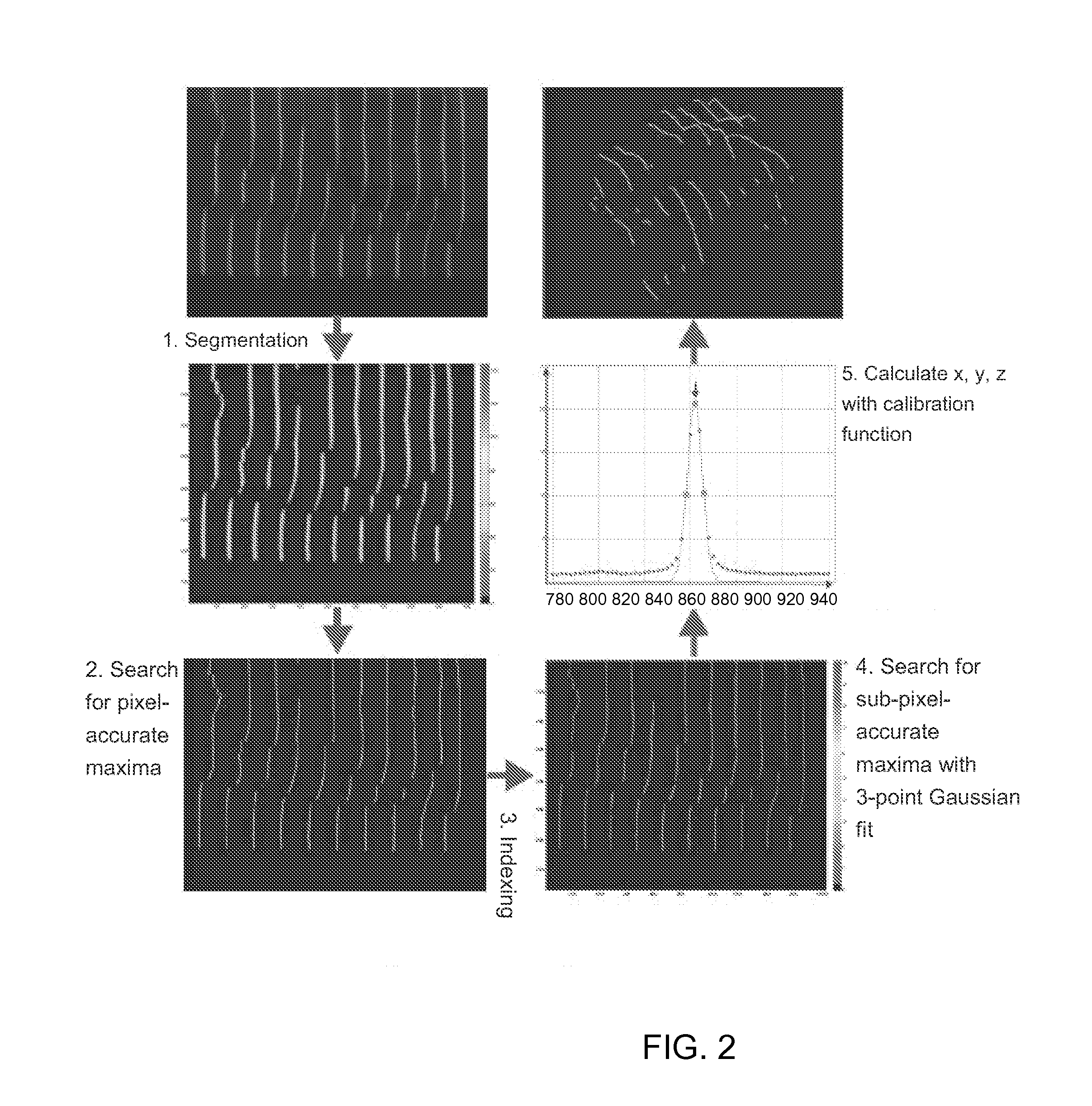
[0074]Referring now to the figures of the drawing in detail and first, particularly, to FIG. 1 thereof, there is seen a flow chart with a workflow sequence of the flying triangulation principle with reference to the acquisition of dental information. In a first step, a geometrical calibration of the sensor is performed and the parameters are determined that are necessary to obtain 3D data from the camera images. Beginning with the first acquired camera image, an algorithm calculates a 3D view from each 2D camera image. That result is displayed in FIG. 2.

[0075]Initially, a preview of the unregistered (i.e., non-aligned) 3D data is displayed live to the user (e.g., two to four 3D data sets, not the camera images), in order to allow the proper positioning of the sensor. In the alternative, it is also possible to display a camera image (or video) in order for the user to immediately see the proper positioning of the sensor. After initiating the measuring sequence, an indexing module det...


PUM


Abstract

The surface shape of a three-dimensional object is acquired with an optical sensor. The sensor, which has a projection device and a camera, is configured to generate three-dimensional data from a single exposure, and the sensor is moved relative to the three-dimensional object, or vice versa. A pattern is projected onto the three-dimensional object and a sequence of overlapping images of the projected pattern is recorded with the camera. A sequence of 3D data sets is determined from the recorded images and a registration is effected between subsequently obtained 3D data sets. This enables the sensor to be moved freely about the object, or vice versa, without tracking their relative position, and to determine a surface shape of the three-dimensional object on the fly.

Description

CROSS-REFERENCE TO RELATED APPLICATION[0001]This application claims the benefit, under 35 U.S.C. §119(e), of my copending provisional patent application 61 / 182,927, dated Jun. 1, 2009. The earlier application is herewith incorporated by reference in its entirety.BACKGROUND OF THE INVENTION[0002]1. Field of the Invention[0003]The invention relates to a method and a device for scanning and digitizing three-dimensional surfaces. The invention is applicable, in particular, to any implementation in which a surface in three-dimensional space may be digitally acquired and processed.[0004]2. Description of the Related Art[0005]Most existing optical 3D sensors require the acquisition of multiple 2D camera images in order to obtain 3D data. The most common technique is the so-called “fringe projection” technique [ref M. Halioua, H. Liu, V. Srinivasan, “Automated phase-measuring profilometry of 3-D diffuse objects,” in Appl. Opt. 23 (1984) 3105-3108], which is widely commercially available, fo...

Claims


Application Information

Patent Timeline
IPC IPC(8): G06K9/00H04N13/02
CPCA61B5/0062A61B5/1077A61B5/1079A61B5/4547G01B11/2513G06T7/521G01B11/2531G06T2207/10016G06T2207/10028G06T2207/30036G06T7/33G01B11/2522
Inventor HAUSLER, GERD
Owner DENTSPLY SIRONA INC
Why Eureka
Try Eureka