
Delimitation barrier, particularly for motor driving circuits

a technology for separating barriers and motor vehicles, applied in roadway safety arrangements, roads, construction, etc., can solve problems such as laborious action on individual dividing elements, awkward removal of the top part of the dividing elements, and difficulty in separating them with cutters or similar tools, so as to achieve convenient and practical use.

Inactive Publication Date: 2010-12-02
IMAGE SERVICES
View PDF15 Cites 2 Cited by
  • Summary
  • Abstract
  • Description
  • Claims
  • Application Information

AI Technical Summary

Benefits of technology

[0013]The aim of the present invention is to solve the problems and obviate the drawbacks cited above, by providing a delimitation barrier, particularly adapted for providing lateral protections in motor racing circuits, that is considerably easier and more practical to use than known types of protective barrier.
[0014]Within this aim, an object of the invention is to provide a delimitation barrier, particularly adapted for providing lateral protections in motor racing circuits, that is reliable and in which the individual elements are simple to obtain and assemble.
[0015]Another object of the invention is to provide a delimitation barrier, particularly adapted for providing lateral protections in motor racing circuits, that has a competitive production cost, so as to make its use advantageous also from an economic standpoint.

Problems solved by technology

In some cases, stacks of tires are used as protective barriers, but they have environmental and functional problems, since in certain situations they are unable to cushion the impact effectively.
First of all, it is very laborious to act on the individual dividing elements to obtain, at the respective longitudinal ends, the openings into which the connecting straps are to be passed.
Moreover, it is likewise awkward to have to remove, by means of cutters or similar tools, the top part of the dividing elements in order to be able to mutually connect the connecting straps.
Obviously, in order to be able to provide, as usual, such plastics dividing elements, it is necessary to use large molds and typically rotary molding, which, as is known, requires extremely long times to mold a single part.
Moreover, if some parts of dividing elements are damaged as a consequence of an impact, it is necessary to replace fully the damaged part, with an evident expenditure of time (required to remove the dividing element or elements to be replaced, by extracting the connecting belts) and of cost.

Method used


Image

  • Delimitation barrier, particularly for motor driving circuits
  • Delimitation barrier, particularly for motor driving circuits
  • Delimitation barrier, particularly for motor driving circuits

Examples


Embodiment Construction

[0024]In the exemplary embodiments that follow, individual characteristics, given in relation to specific examples, may actually be interchanged with other different characteristics that exist in other exemplary embodiments.

[0025]Moreover, it is noted that anything found to be already known during the patenting process is understood not to be claimed and to be the subject of a disclaimer.

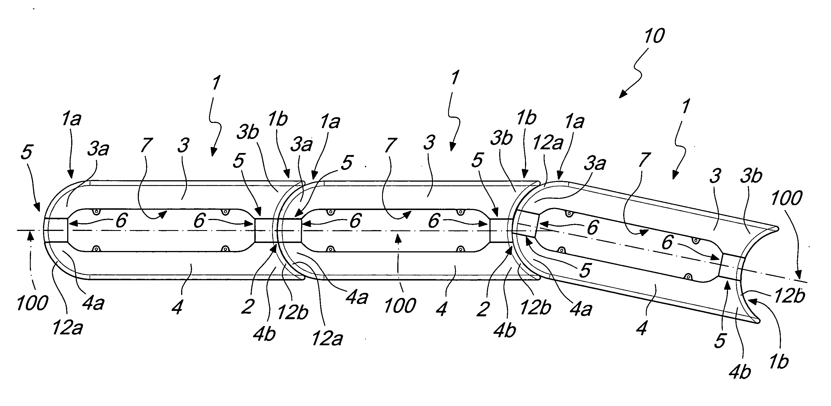
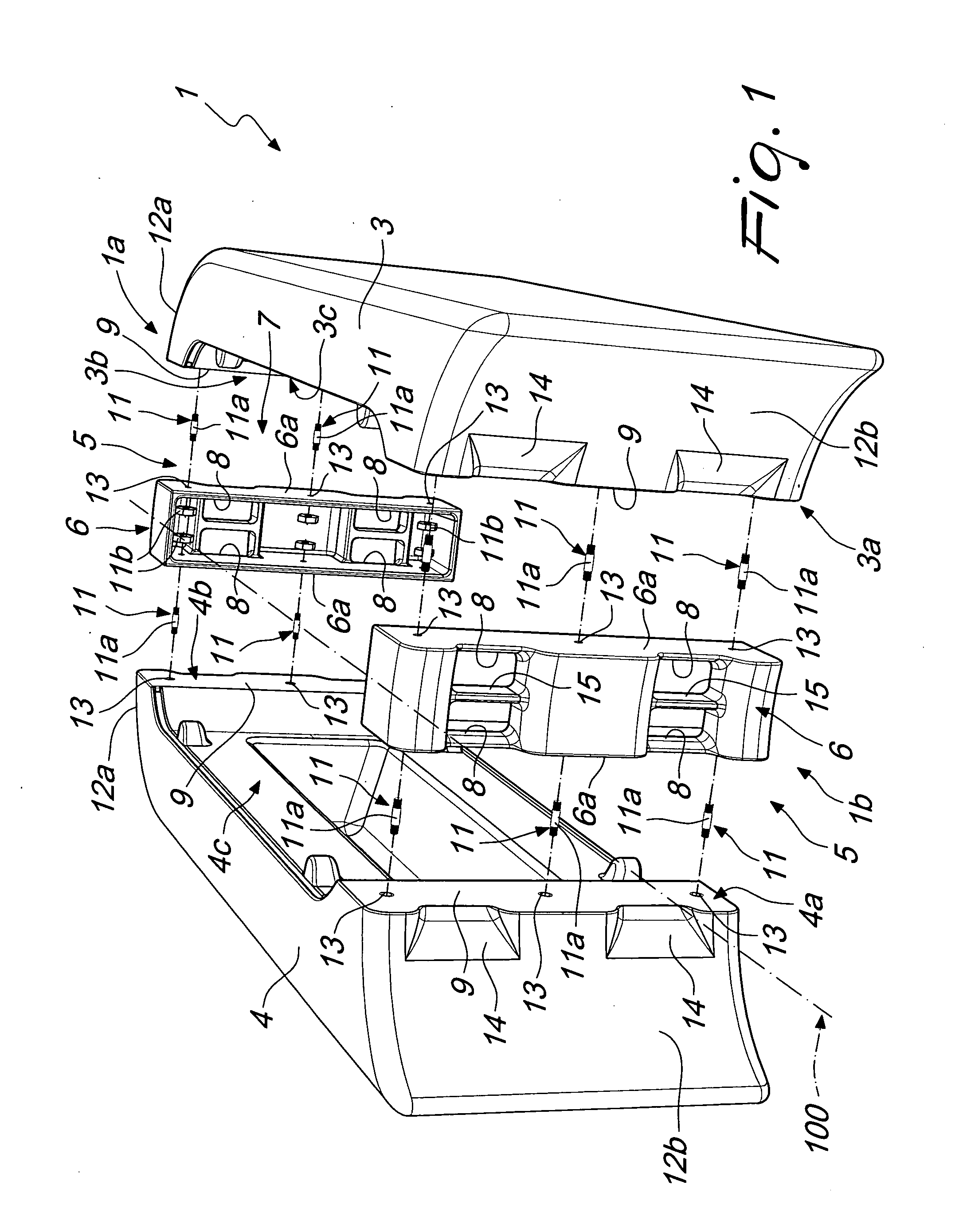
[0026]With reference to the figures, a delimitation barrier, particularly adapted for providing lateral protections in motor racing circuits and generally designated by the reference numeral 10, comprises a plurality of dividing elements 1, which have an elongated shape and are extended along a substantially longitudinal direction of extension that is designated by the reference numeral 100 in the figures.

[0027]The dividing elements 1 are mutually connected, by way of mutual interconnection means 2 described hereinafter, substantially at the respective longitudinal ends 1a and lb.

[0028]According to ...


PUM


Abstract

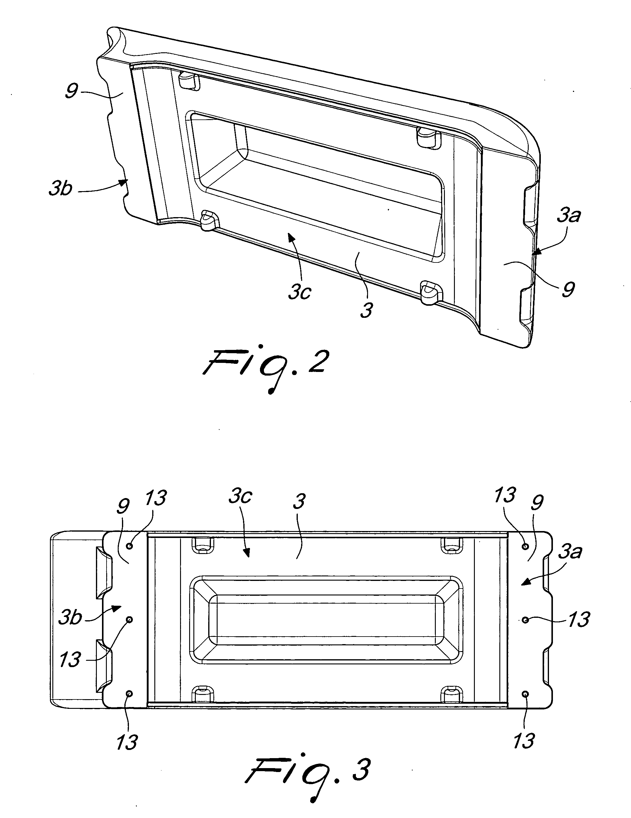
A delimitation barrier, particularly adapted for providing lateral protections in motor racing circuits, which comprises a plurality of dividing elements that are extended along a substantially longitudinal direction of extension and are mutually connected, by way of mutual interconnection elements, substantially at the respective longitudinal ends; at least one of the dividing elements comprises at least one first lateral body and at least one second lateral body, which can be mutually connected by way of mutual connection elements and are arranged, during use, predominantly on opposite sides with respect to the substantially longitudinal direction of extension of the respective dividing element.

Description

[0001]The present invention relates to a delimitation barrier, particularly adapted for providing lateral protections in motor driving circuits, such as autodromes, kartdromes and circuits in general.BACKGROUND OF THE INVENTION[0002]Protective barriers are currently known and widely used in the types of circuit cited above and can be placed at regions of the circuit that are particularly dangerous in case of runoffs and have the purpose of cushioning the impact and at the same time of stopping the motion of the vehicle, absorbing part of the kinetic energy as a consequence of the runoff.[0003]In some cases, stacks of tires are used as protective barriers, but they have environmental and functional problems, since in certain situations they are unable to cushion the impact effectively.[0004]Protective barriers have thus been proposed which are constituted substantially by a plurality of dividing elements, generally made of plastics and internally hollow so as to contain a certain vol...

Claims


Application Information

Patent Timeline
IPC IPC(8): E01F15/02
CPCE01F15/086E01F15/088
Inventor SEVERGNINI, GIUSEPPE SECONDO
Owner IMAGE SERVICES
Learn More