Pipe stand transfer systems and methods

a transfer system and pipe stand technology, applied in the direction of transportation and packaging, drilling pipes, drilling rods, etc., can solve the problems of high construction cost and their operation, and achieve the effect of facilitating the movement of the pipe handling head

Active Publication Date: 2010-12-02
NAT OILWELL VARCO LP
View PDF62 Cites 81 Cited by
  • Summary
  • Abstract
  • Description
  • Claims
  • Application Information

AI Technical Summary

Benefits of technology

[0015]An aspect of the invention provides a pipe handler for handling pipe in a fingerboard, the fingerboard having a plurality of spaced-apart fingers for supporting a plurality of tubulars, e.g. pieces of pipe, the pipe handler including: a pipe handling head having a head width; a distance comprising a second width, the second width including the distance between two fingers of the finger board and twice the width of one finger; and the head width less than the second width to facilitate movement of the pipe handling head along a row between the two fingers.

Problems solved by technology

A variety of difficulties and dangers can be associated with procedures for running a drill string into or out of a well bore to personnel involved in these procedures, e.g., personnel working on a platform above a drilling rig floor.
Several of the known devices are cumbersome in their design and, thus, in their operation and are expensive to build.

Method used


Image

  • Pipe stand transfer systems and methods
  • Pipe stand transfer systems and methods
  • Pipe stand transfer systems and methods

Examples


Embodiment Construction

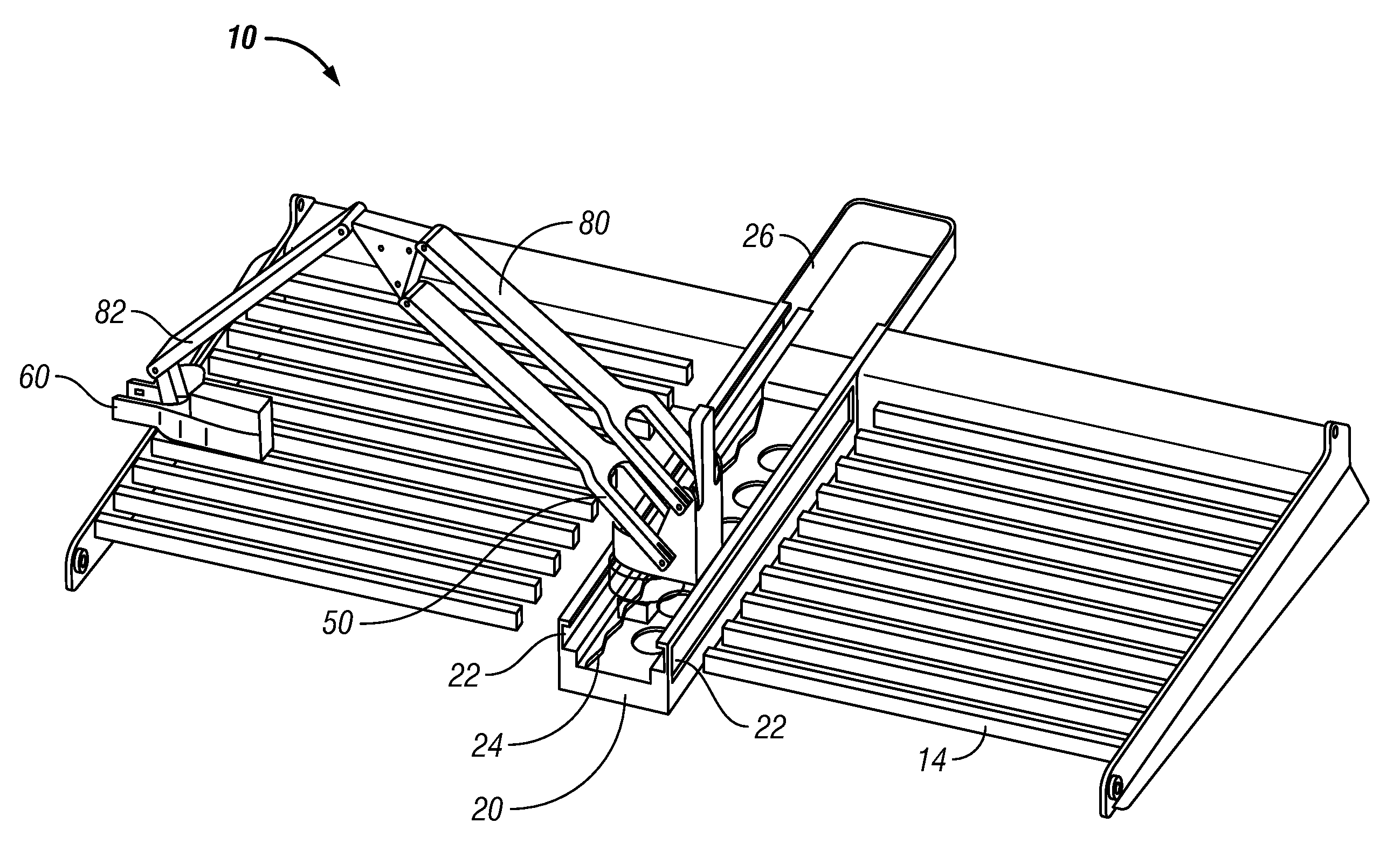
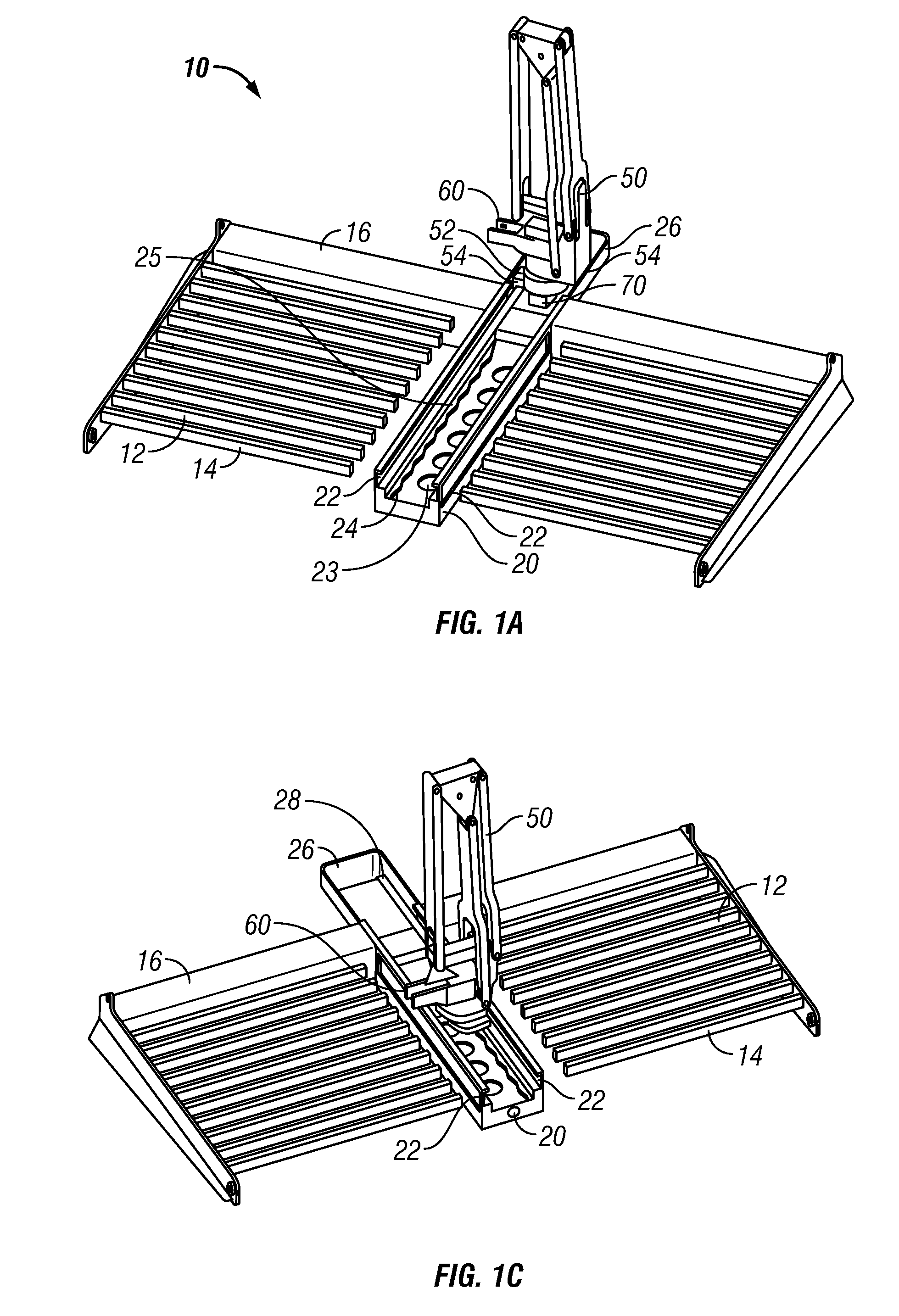
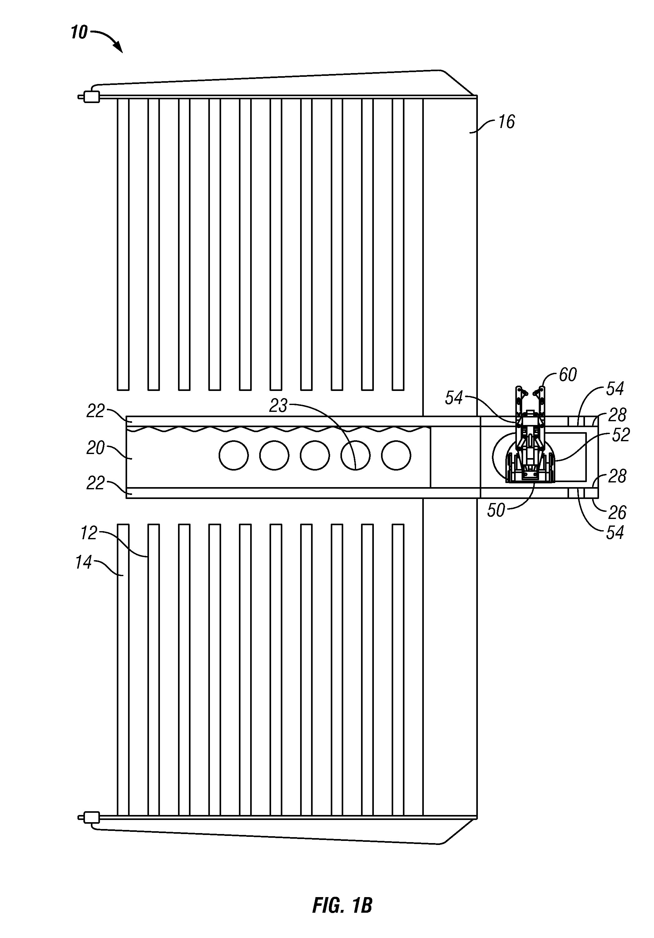
[0052]Referring now to FIG. 1, a system 10 according to the present invention has a track 20 mounted between rows 12 of fingers 14 of a fingerboard 16. A pipe handler 50 according to the present invention is movably mounted on the track 20. The pipe handler 50 has a carriage 52 with rotatable rollers 54 which roll in channels 22 of the track 20.

[0053]As discussed in detail below, a selectively locking mechanism 70 of the pipe handler 50 (or mechanisms 70) engages a lock rim 24 (or rims) of the track 20. The pipe handler 50 has a pipe handling head 60.

[0054]As shown in FIGS. 1A, 1C, and 1E, the pipe handler 50 is movable on the track 20 so that the pipe handling head 60 can access any pipe or stand of pipes supported by the fingerboard 16. As shown in FIGS. 1D, 1E, 1F, 2A, 5 and 6, the pipe handler 50 is extendable so that the pipe handling head 60 can move pipe or a stand of pipe to a desired location.

[0055]As shown in FIG. 1A, the track 20 is located below a level of the fingers 14...


PUM


Abstract

Methods and systems for transferring pipe (including tubulars such as casing, tubing, drill pipe, etc.) or stands of pipe from one location to another in a wellbore derrick, e.g. from a fingerboard to a well center.

Description

BACKGROUND OF THE INVENTION[0001]1. Field of the Invention[0002]The present invention is directed to systems for moving tubulars and pipe stands in a derrick; to systems for transferring a tubular or a stand of pipe between a fingerboard area and a well center; and to methods of the use of such systems.[0003]2. Description of Related Art[0004]A wide variety of drilling systems, apparatus, and methods are known, including, but not limited to, the disclosures in U.S. Pat. Nos. 6,944,547; 6,918,453; 6,802,378; 6,050,348; 5,465,799; 4,995,465; 4,854,397; 4,850,439; and 3,658,138. A wide variety of tubular handling and tubular transfer systems for wellbore operations are known; for example, and not by way of limitation, those disclosed in U.S. Pat. Nos. 7,293,607; 7,137,454; 7,083,007; 6,976,540; 6,821,071; 6,779,614; 5,988,299; 5,451,129; 4,862,973; 4,765,401; 4,725,179; 4,462,733; 4,345,864; 4,274,778; 4,269,554; 4,128,135; 4,044,895; 4,042,123; 4,013,178; and in U.S. Patent Applicatio...

Claims


Application Information

Patent Timeline
Patent Type & Authority Applications(United States)
IPC IPC(8): E21B19/00
CPCE21B19/14
Inventor HANKINS, JOHN BENJAMINWINTER, BRIAN DANIELGROSZ, GREGORY CHRISTOPHER
Owner NAT OILWELL VARCO LP
Why Eureka
Try Eureka