Electronic device and flexible printed wiring board
a technology of flexible printed wiring board and electronic device, which is applied in the direction of circuit bendability/stretchability, fixed connection, coupling device connection, etc., can solve the problems of reducing convenience, no consideration of how to guide the connector along the width of the wiring board, and no means for guiding the flexible printed wiring board
- Summary
- Abstract
- Description
- Claims
- Application Information
AI Technical Summary
Benefits of technology
Problems solved by technology
Method used
Image


Examples
first embodiment
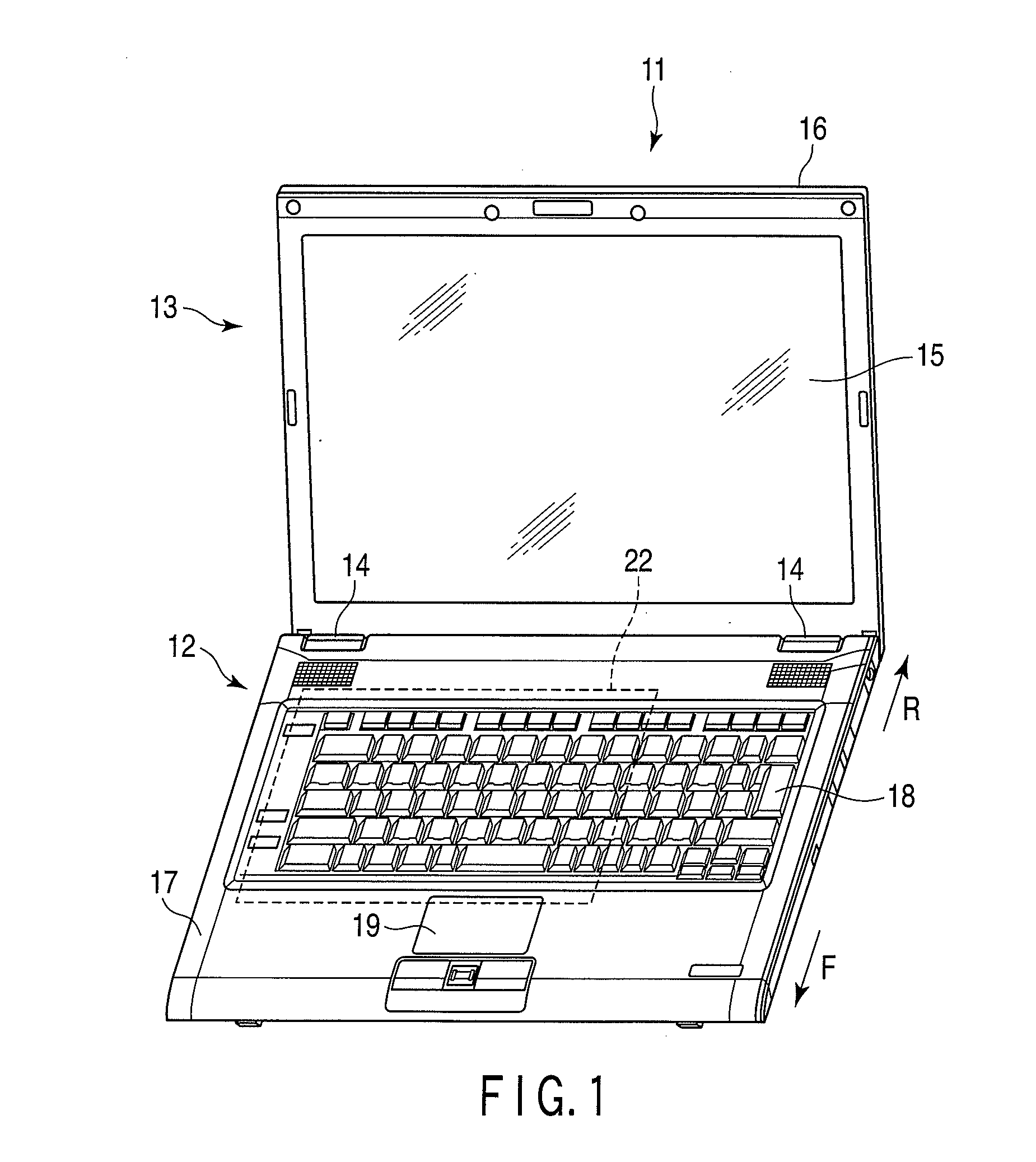
[0026]Referring now to FIGS. 1 to 8, an electronic device will be described. In the description below, the near side to the user (that is, user side) is defined as front F, the far side from the user is rear R, the left-hand side of the user is left, the right-hand side of the user is right, the upper side from the user's position is up and the lower side from the user's position is down.
[0027]As shown in FIG. 1, a portable computer 11 as an example of the electronic device of the first embodiment comprises a main unit 12, a display unit 13, and hinges 14 provided between the main unit 12 and the display unit 13. The hinges 14 support the display unit 13 so that the display unit can rotate.
[0028]As shown in FIG. 1, the display unit 13 comprises a liquid crystal display 15 as a display example, and a synthetic resin cover 16 enclosing the liquid crystal display 15.
[0029]As can be seen from FIGS. 1 and 2, the main unit 12 comprises a case 17 as an outer envelope, a keyboard 18 and a ...
second embodiment
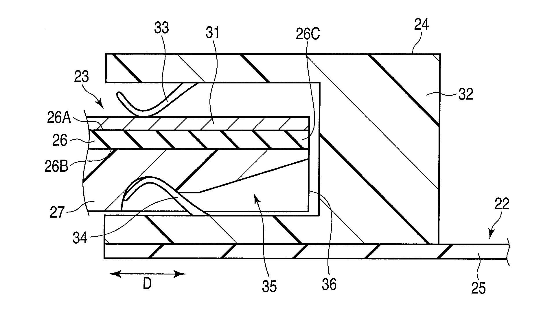
[0053]The connector 24 is a so-called top and bottom double contacts type connector. In the second embodiment, the first contacts 61 are made to be brought into contact with conductors 31, and the second contacts 62 are made to be brought into contact with a reinforcing plate 27. However, this may be modified such that the first contacts 61 are made to be brought into contact with the reinforcing plate 27, and the second contacts 62 are made to be brought into contact with the conductors 31.
[0054]In the second embodiment, when the front end 26C of the flexible printed wiring board 23 is inserted into the connector 24, the tip of the second contact 62 enters the opening 42 of the recess portion 35. When the front end 26C of the flexible printed wiring board 23 is further forwarded, the second contact 62 is guided along the tilted surface 41A of the recess portion 35. Since in the second embodiment, the first and second contacts 61 and 62 are fixed in position, the flexible printed wi...
third embodiment
[0063]In the above-described third embodiment, each recess portion 35 includes the through hole 71 formed in the portion of the reinforcing plate 27 away from the opening 42, and formed through the reinforcing plate 27 along the thickness of the same. This structure enables the flexible printed wiring board 23 to be prevented from being unintentionally disengaged from the connector 24.
[0064]Further, when the flexible printed wiring board 23 is most deeply inserted in the connector 24 to thereby cause the second contacts 34 to be press-fitted into the through holes 71, the user can confirm that the flexible printed wiring board 23 has been correctly inserted in the connector 24. Furthermore, since in the third embodiment, the through holes 71 are provided in place of the recesses 43 of the first embodiment, it is not necessary to delicately adjust the energy of the laser and / or the number of shorts of the laser to form the recesses 43. The through holes 71 can be easily formed by dri...
PUM
 Abstract
Description
Claims
Application Information
 - R&D
- Intellectual Property
- Life Sciences
- Materials
- Tech Scout
- Unparalleled Data Quality
- Higher Quality Content
- 60% Fewer Hallucinations
Browse by: Latest US Patents, China's latest patents, Technical Efficacy Thesaurus, Application Domain, Technology Topic, Popular Technical Reports.
© 2025 PatSnap. All rights reserved.Legal|Privacy policy|Modern Slavery Act Transparency Statement|Sitemap|About US| Contact US: help@patsnap.com