Method for selective antenna activation and per antenna or antenna group power assignments in cooperative signaling wireless MIMO systems

a wireless mimo and antenna activation technology, applied in the field of multi-input multiple output (mimo) wireless systems, can solve the problems of limiting the rate at which a user can be served, and affecting the service quality of users

Inactive Publication Date: 2010-12-02
NTT DOCOMO INC
View PDF11 Cites 34 Cited by
  • Summary
  • Abstract
  • Description
  • Claims
  • Application Information

AI Technical Summary

Problems solved by technology

Thus, different groups (of stations or antennas) generally interfere with each other over the wireless channel.
Interference is a common, well-known, inherent problem in many wireless transmission systems given the common broadcast nature of the wireless medium.
Interference can significantly limit the rates at which a user can be served.
However, with non-zero interference the interference is often at a level determined by transmissions from non-cooperating stations (antennas).
The use of frequency reuse, however, to reduce interference comes at the expense of efficiency in terms of the term “(1 / F)”, as seen directly as a pre-log term in the capacity formula.
However, there is an unequal power split between bands.
Now only inter-cluster interference remains, and is mainly a problem at cluster edges, not all cell edges.
While certainly useful there is, however, one drawback in doing a cluster based approach and power mask in the way described.
This may not be the best way to use a pool of transmission power across frequencies, antennas and coordination patterns.
A static DAS system, as described in FIG. 6 and Table 5 below, may not be as effective as a cluster system as in FIG. 4 or FIG. 5 because the DAS system also can see increases in interference near cell edges despite allowing servicing antennas to be brought nearer to users.
Such a tradeoff can be detrimental for cell edge users, and these users need to be served.

Method used


Image

  • Method for selective antenna activation and per antenna or antenna group power assignments in cooperative signaling wireless MIMO systems
  • Method for selective antenna activation and per antenna or antenna group power assignments in cooperative signaling wireless MIMO systems
  • Method for selective antenna activation and per antenna or antenna group power assignments in cooperative signaling wireless MIMO systems

Examples


Embodiment Construction

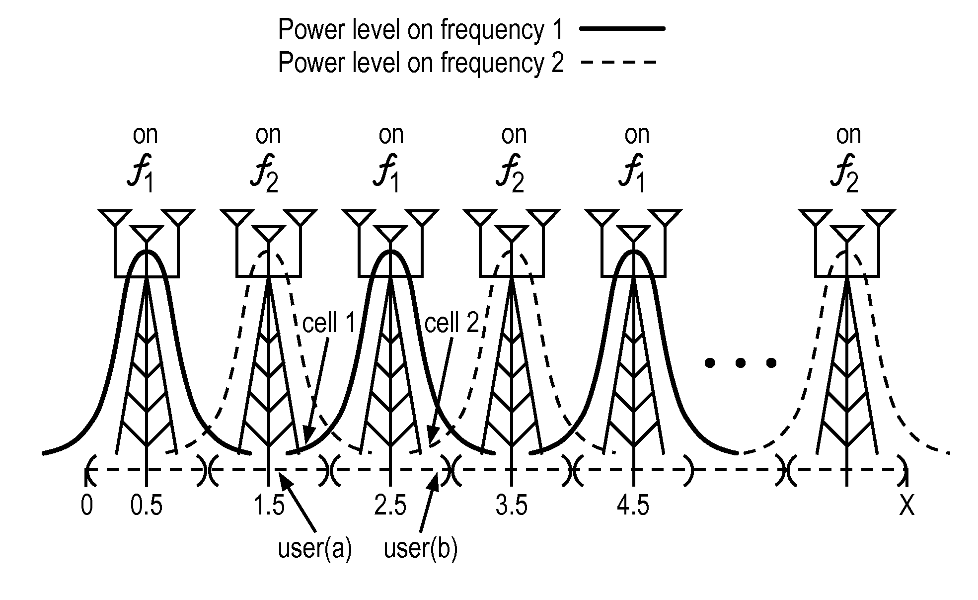
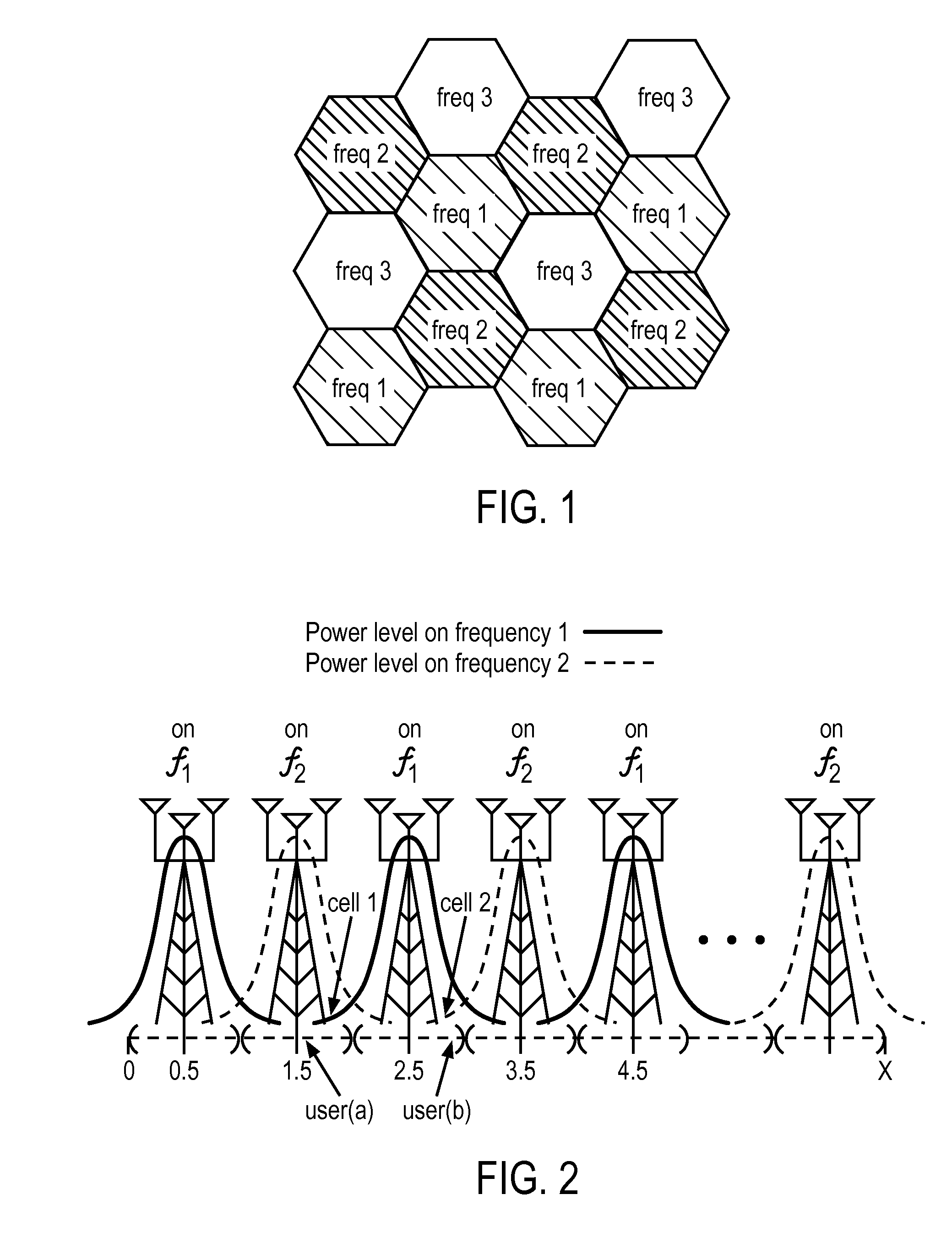
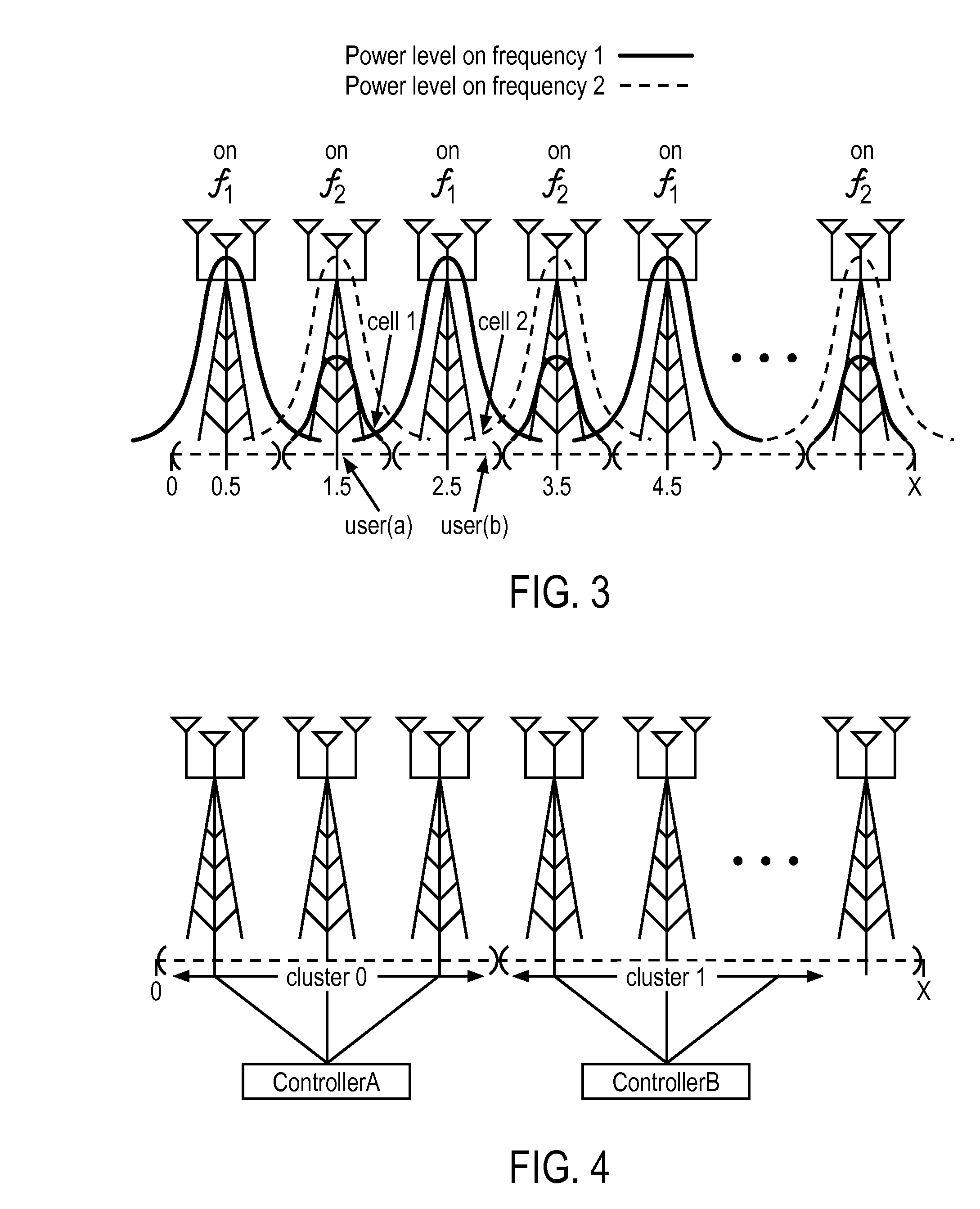
[0050]Embodiments of the invention include a method by which antennas distributed across a geographic area are selectively activated across frequency and / or time, with a specified power to each antenna when active as a function of frequency and / or time, in order to achieve an improved balance of resources of such power and antennas, thereby allowing the system to improve wireless efficiency. In one embodiment, the antennas that are activated, and the power per antenna, changes with time and / or frequency in a purposeful and advantageous way that balances the benefits of interference mitigation to the service needs of different users. Specifically, sometimes users are given an advantage at the expense of other users, and sometimes those same users are put at a disadvantage to the benefit of other users. By matching power correctly to the number of antennas and interference levels, a better use of the wireless resource can be obtained. The net result is often net benefit to all users. ...


PUM


Abstract

A method and apparatus is disclosed herein for selective antenna activation in cooperative signaling wireless systems. In one embodiment, the method is for use in a cooperative signaling MIMO system in which antennas are located a plurality of different locations across a geographic area, the system comprising a plurality of different cooperative MIMO controllers and a plurality of antennas that can be communicably coupled to each of the controllers, the method comprising: at different transmission instances, selectively activating one or more antennas in the cooperative signaling MIMO system to vary which subset of antennas are active among antennas that can be used for each of the controllers in the system, including applying a power pattern which specifies per antenna or per antenna group power assignments for the one or more antennas being selectively activated, and performing cooperative MIMO transmission under control of at each controller in conformance with antenna activation and antenna power assignments assigned for each transmission time.

Description

PRIORITY[0001]The present patent application claims priority to and incorporates by reference the corresponding provisional patent application Ser. No. 61 / 181,595, titled, “A Method for Selective Antenna Activation and Per Antenna or Per Antenna Group Power Assignments in Cooperative Signaling Wireless MIMO Systems,” filed on May 27, 2009.FIELD OF THE INVENTION[0002]Embodiments of the present invention relate to the field of Multiple Input Multiple Output (MIMO) wireless systems; more particularly, embodiments of the present invention relate to techniques where a number of coordinated / cooperative-signaling antennas are used to serve a coverage area containing multiple users.BACKGROUND OF THE INVENTION[0003]In some wireless communication systems, groups of antennas (e.g., a number of antennas across a set of cooperative base-stations) cooperate in transmissions to jointly serve users contained within a coverage area. It is assumed that antennas belonging to different groups do not co...

Claims


Application Information

Patent Timeline
Patent Type & Authority Applications(United States)
IPC IPC(8): H04B7/005
CPCH04B7/024H04B7/026H04B7/0426H04B7/0691H04B7/0874
Inventor RAMPRASHAD, SEAN A.
Owner NTT DOCOMO INC
Why Eureka
Try Eureka