

Screwdriver bit structure having auxiliary positioning function
a technology of auxiliary positioning and screwdriver, which is applied in the direction of screwdrivers, wrenches, manufacturing tools, etc., can solve the problems that the protruding ring section cannot be rotated individually, whether the protruding ring section is integrated with or connected to the circular shaft, etc., and achieves effective and stably rotating
- Summary
- Abstract
- Description
- Claims
- Application Information
AI Technical Summary
Benefits of technology
Problems solved by technology
Method used
Image

Examples
Embodiment Construction
[0025]Other features and advantages of the present invention will become apparent from the following description of the invention which refers to the accompanying drawings.
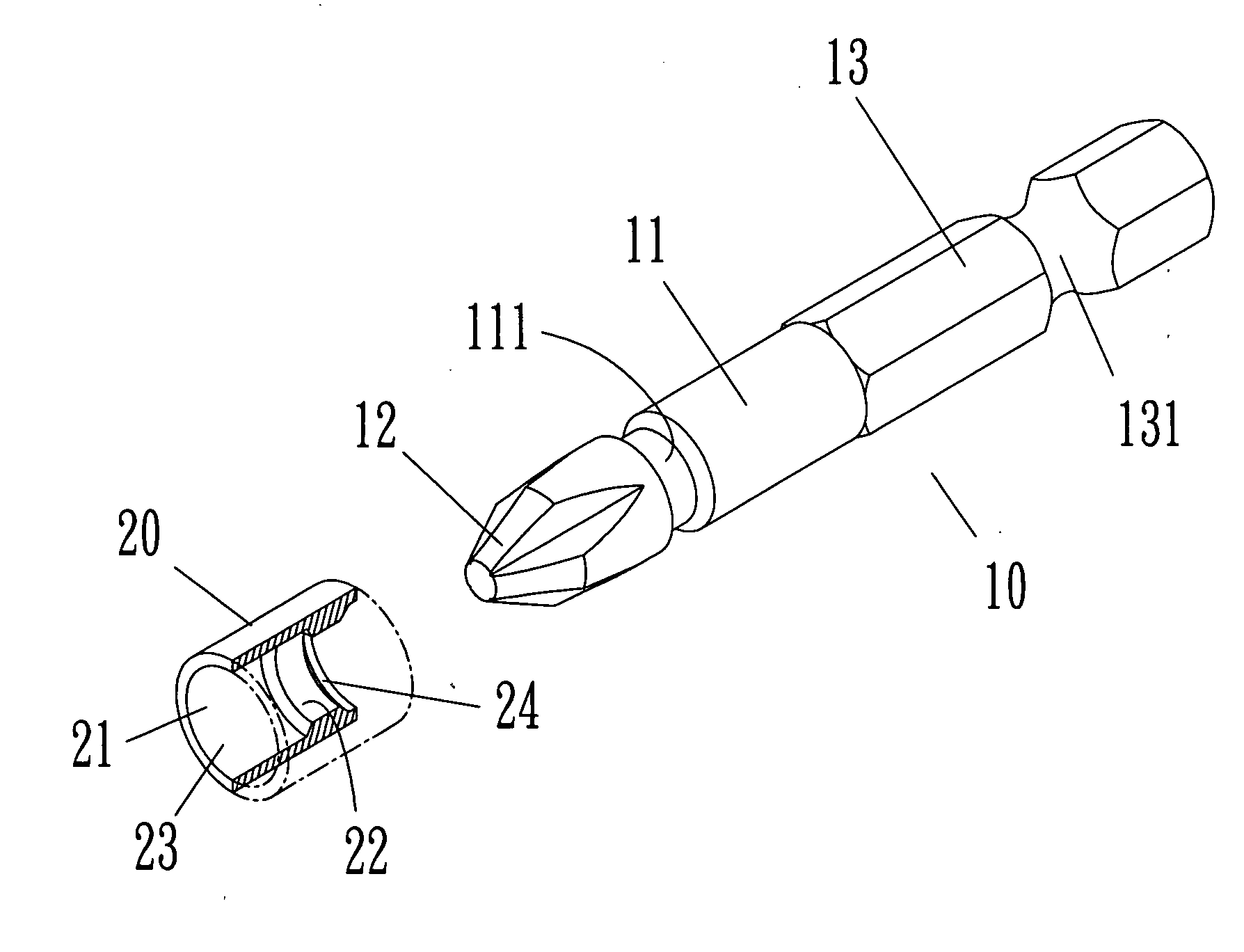
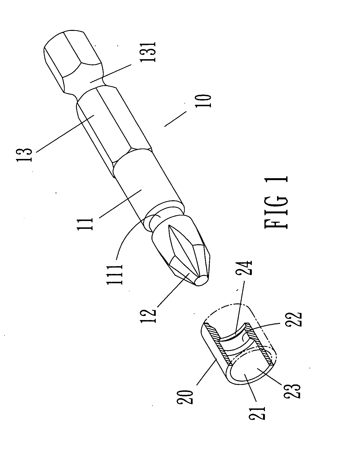
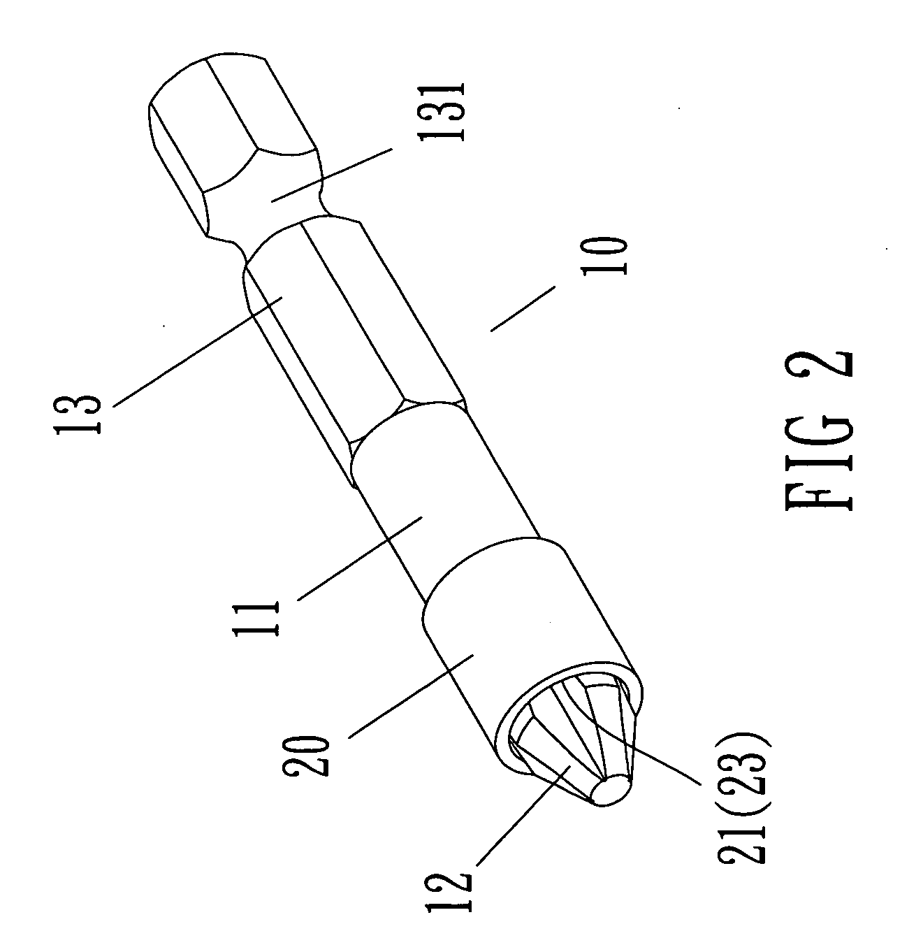
[0026]First, please refer to FIG. 1 to FIG. 4, a screwdriver bit structure having auxiliary positioning function is shown according to a preferred embodiment I of the present invention, and composed of a screwdriver bit 10 and an auxiliary sheath 20. An end of the screwdriver bit 10 is a circular cylinder 11. A front of the circular cylinder 11 has a driving portion 12. Another end of the circular cylinder 11 is a fitting portion 13. The front of the driving portion 12 is any one of a slotted type, a cross type, and a polygon type. The circular cylinder 11 has a concave ring groove 111 near the front of the driving portion 12. The fitting portion 13 of the circular cylinder 11 is a polygon column. An arc groove 131 is further disposed to a middle section of the polygon column so as to connect a screwdriver bar (no...
PUM
 Abstract
Description
Claims
Application Information