
Piston having oil supply channel for hub bore holes

a technology of hub bore hole and oil supply channel, which is applied in the direction of trunk piston, machine/engine, plunger, etc., can solve the problems of insufficient supply of splash oil, difficult access, and difficult direct supply of lubricating oil in regions, etc., and achieves simple and cheap manners

Inactive Publication Date: 2010-12-09
FEDERAL MOGUL NURNBERG GMBH
View PDF21 Cites 0 Cited by
  • Summary
  • Abstract
  • Description
  • Claims
  • Application Information

AI Technical Summary

Benefits of technology

[0008]It is an object of the invention to improve the lubricating oil supply of the bolt opening / bolt and bolt / upper connecting rod eye portions that are subject to friction.
[0012]Preferably, a retaining ring (locking ring) may be inserted into the bolt opening. The retaining ring prevents unwanted displacement of the bolt.
[0013]Preferably, at least one oil guide opening is provided in the cylindrical piston, which connects the cavity or lateral recess with the oil channel. Such an oil guide opening provides a suitable means for supplying the cavity and possibly the lateral recesses of the bolt opening with oil in a targeted manner. In this way, the bolt not only receives oil from the direction of the outer piston side but also from the direction of the inner piston side. Therefore, the lubricant may disperse in a particularly easy manner along the piston also between the frictional surfaces of the bolt and the small connecting rod eye. Further, the oil present in the cavity and possibly in the lateral recesses of the cavity also serves as splash oil which is particularly likely to reach the regions to be lubricated or bolt openings / bolts and bolt / upper connecting rod eye due to its close distance (vicinity).
[0014]Preferably, the oil guide opening and the bolt opening are formed continuously. A continuous configuration of the bolt opening and the oil guide opening is advantageous from the point of view of manufacture. The oil is, thus, conducted behind the retaining ring into the lateral recesses and the cavity, respectively.
[0015]Preferably, the oil guide is a groove. Introducing a groove into the circumferential area of the piston is a simple and cheap manner to provide an oil guide according to the present invention.

Problems solved by technology

Here, the movable portions between the bolt opening / bolt and bolt / upper connecting rod eye need to be emphasized as lubrication is absolutely necessary in these regions but a direct supply of lubricating oil is difficult.
The reason for this is that these regions are subject to a permanent up-and-down movement and are, thus, difficult to access.
In the prior art, due to this indirect oil supply to the lubricating points around the bolt opening and around the upper (small) connecting rod eye it may happen that these regions can be supplied with splash oil only insufficiently and / or in an undefined manner.

Method used


Image

  • Piston having oil supply channel for hub bore holes
  • Piston having oil supply channel for hub bore holes

Examples


Embodiment Construction

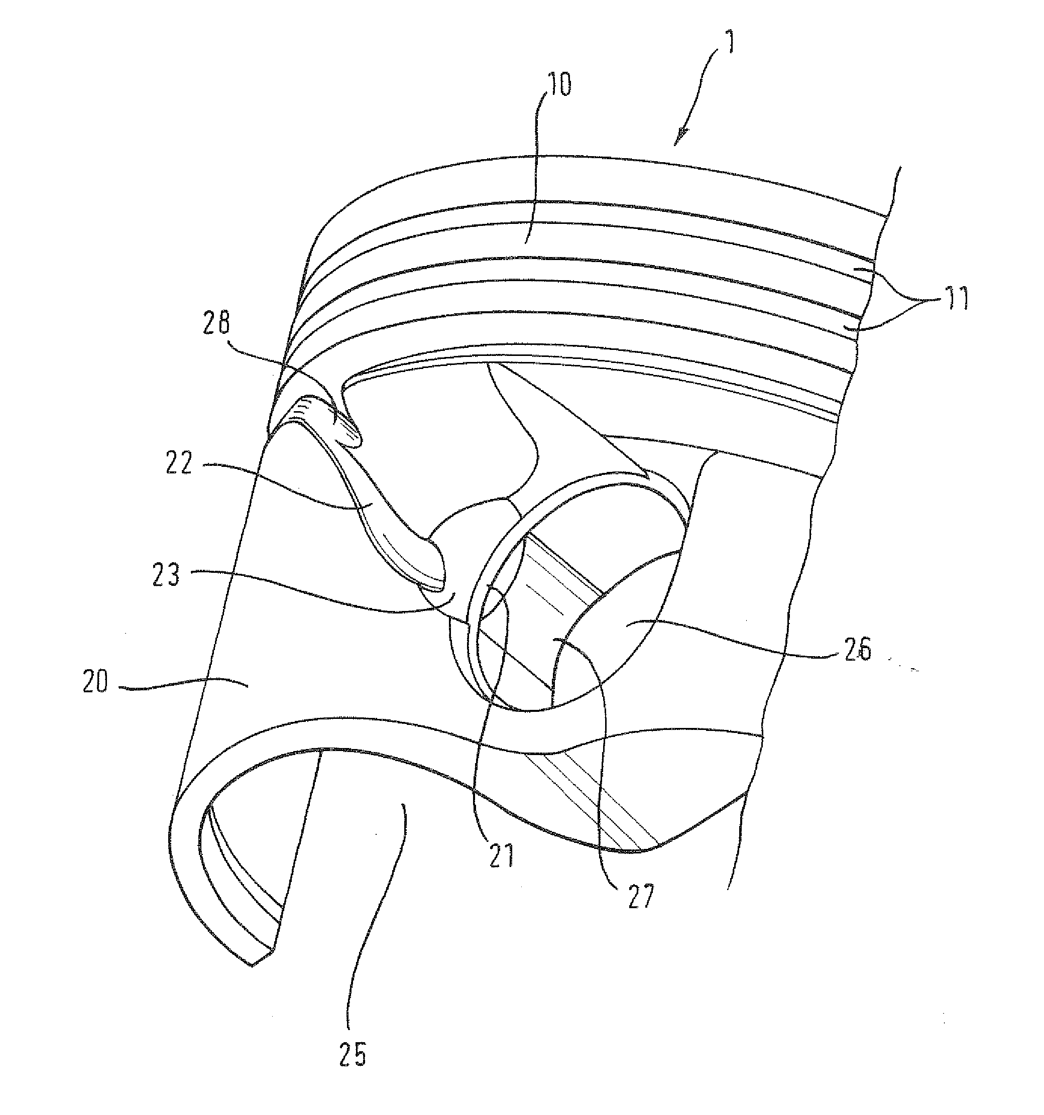
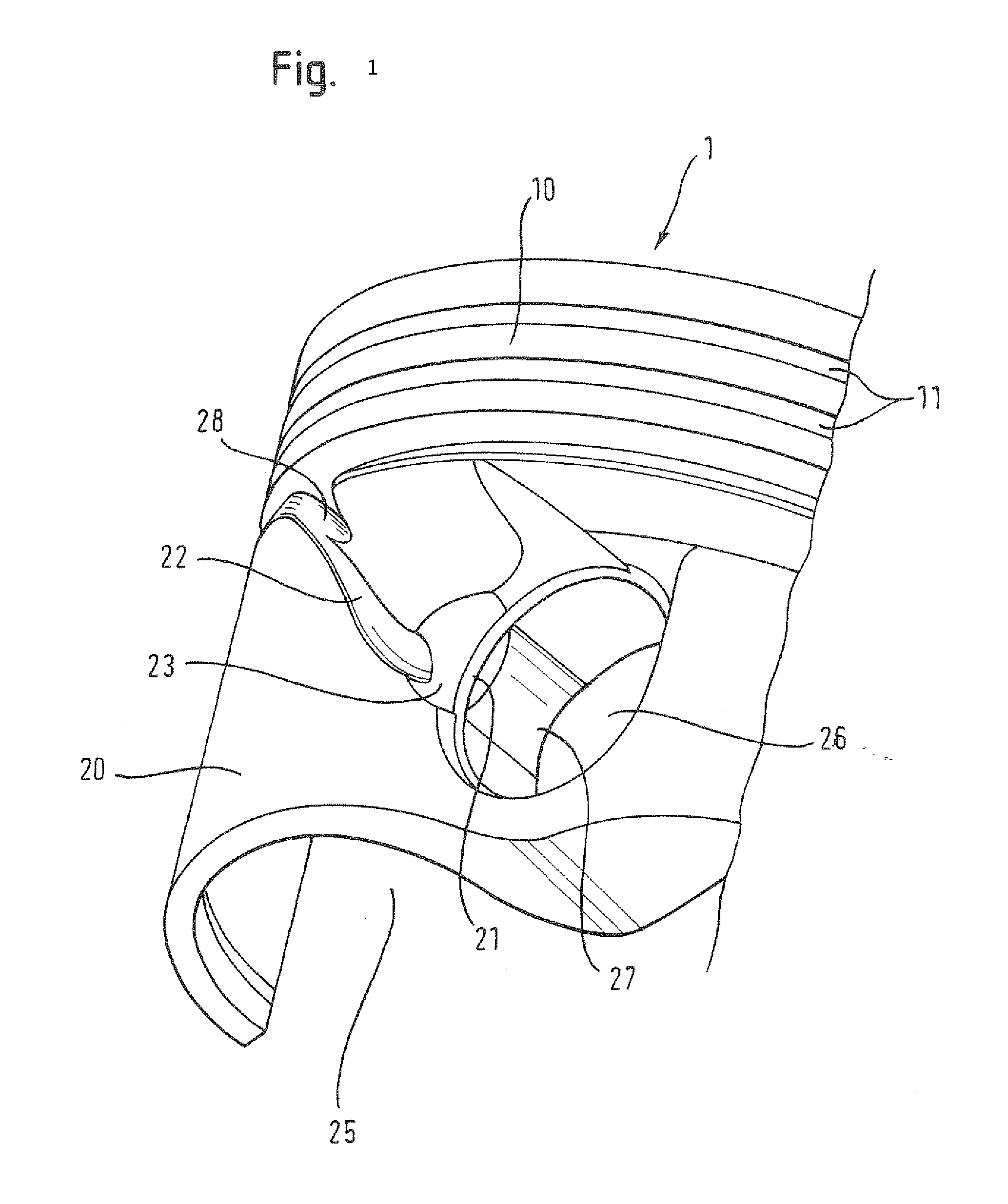
[0021]The FIGURE shows a detail of an inventive piston 1 having a piston crown 10 and a piston base 20. The piston crown is of cylindrical shape and is provided with annular grooves (snap ring grooves) 11 and oil rings which are not shown. In the FIGURE, a piston base 20 having a cavity 25 adjoins the piston crown 10 from below. Like in the present case, the piston base 20 does not need to have any circular cylindrical shape. In the present embodiment, the piston base 20 comprises walls recessed from the periphery and forming a box-shaped piston base. In the peripheral region of the piston base 20, two opposite pin openings 26 for receiving a pin are provided. In the FIGURE, only one part of the piston having a single pin opening 26 is shown. These pin openings 26 can, as shown in the FIGURE, be provided with a locking ring 21 received in a groove formed in the pin opening 26. In the FIGURE, a pin (not shown) is supported in the pin openings 26, which pin serves as axis for the smal...


PUM


Abstract

A cylindrical piston for internal combustion engines, comprising a piston crown and a piston base, in the piston base a hollow space being provided, and in a piston base wall forming the hollow space pinholes being provided, characterized in that the outer circumferential surface in at least the piston base at least one oil guide is provided, the direction thereof having an axial component relative to the piston axis and the oil guide extending from the piston crown in the direction of a pinhole.

Description

TECHNICAL FIELD The invention concerns a piston having an oil duct for an internal combustion engine.PRIOR ART[0001]Pistons for internal combustion engines are exposed to extremely high mechanical and thermal loads during operation so that it has to be ensured that the cylinder and piston portions that are exposed to constant friction due to their motion are sufficiently cooled and lubricated in order to keep friction as low as possible.[0002]One measure is to provide in the piston an annular circumferential cooling channel in the region of the piston crown, for example, into which a cooling means, such as oil can be injected by means of at least one inlet opening. The supply of cooling oil is usually effected during the down stroke, while the piston moves toward an oil spray nozzle. The discharge of oil is usually performed by pressing the oil through inertial forces against the lower side of the cooling channel during the upstroke of the piston and pressing it out of the cooling c...

Claims


Application Information

Patent Timeline
Patent Type & Authority Applications(United States)
IPC IPC(8): F02F3/22
CPCF02F3/00F16J1/16F16J1/08
Inventor BOHM, ROLAND
Owner FEDERAL MOGUL NURNBERG GMBH
Learn More