Polarisation-independent coherent optical receiver
a coherent optical receiver and polarisation-independent technology, applied in electromagnetic transmission, electrical equipment, transmission, etc., can solve the problems of high cost of optical and electronic components, incompatibility with requirements, and considerable complexity
Active Publication Date: 2017-09-05
TELEFON AB LM ERICSSON (PUBL)
View PDF8 Cites 2 Cited by
- Summary
- Abstract
- Description
- Claims
- Application Information
AI Technical Summary
Benefits of technology
This patent aims to create a receiver that works well with different light polarizations and is easy and cheap to make. It doesn't require precise control of the frequency of the signal generated by the local oscillator.
Problems solved by technology
Yet, the currently existing coherent receivers, which have been studied for the transport network, employ sophisticated and hence expensive optical and electronic components, which are therefore incompatible with the requirements of a wide diffusion.
Yet, the prior art receivers discussed above are polarisation sensitive, and hence it is necessary to adopt in them one of the techniques currently employed or proposed for obtaining the independence from the state of polarisation of the received signal in coherent systems.
All such solutions entail a considerable increase in the complexity and hence in the cost, thereby making the receivers incompatible with the requirements of large scale diffusion.
Yet, in the case of the access networks where such a multiplexing is not envisaged, duplicating the receiver structure only results in doubling the manufacturing costs and the energy consumption.
Among the other known techniques, polarisation modulation at the transmitting side (see U.S. Pat. No. 5,127,066) and automatic polarisation alignment (see U.S. Pat. No. 7,307,722) entail using additional components (e.g. polarisation modulators), which are expensive per se and moreover cause degradation of the performance.
Yet, this scheme does not provide for phase diversity and this entails that the receiver has necessarily to be employed in heterodyne mode.
This has considerable drawbacks: first, heterodyne detection requires use of components with wider bands and reduces receiver sensitivity; moreover, it cannot be used in case of modulation formats according to which the signal is in-phase and quadrature (I / Q) modulated; lastly it requires a very precise control of the frequency difference between the signal from the local oscillator and the received signal.
Moreover, the analogue processing of the electrical signals resulting from the photoelectric conversion is rather complex.
Furthermore, use of a heterodyne receiver limits the possibility of use in a wavelength division multiplexing (WDM) system with high channel density.
Method used
View moreImage
Smart ImageViewing Examples
Examples
first embodiment
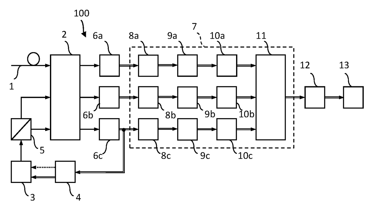
[0017]FIG. 1 is a block diagram of the invention;
second embodiment
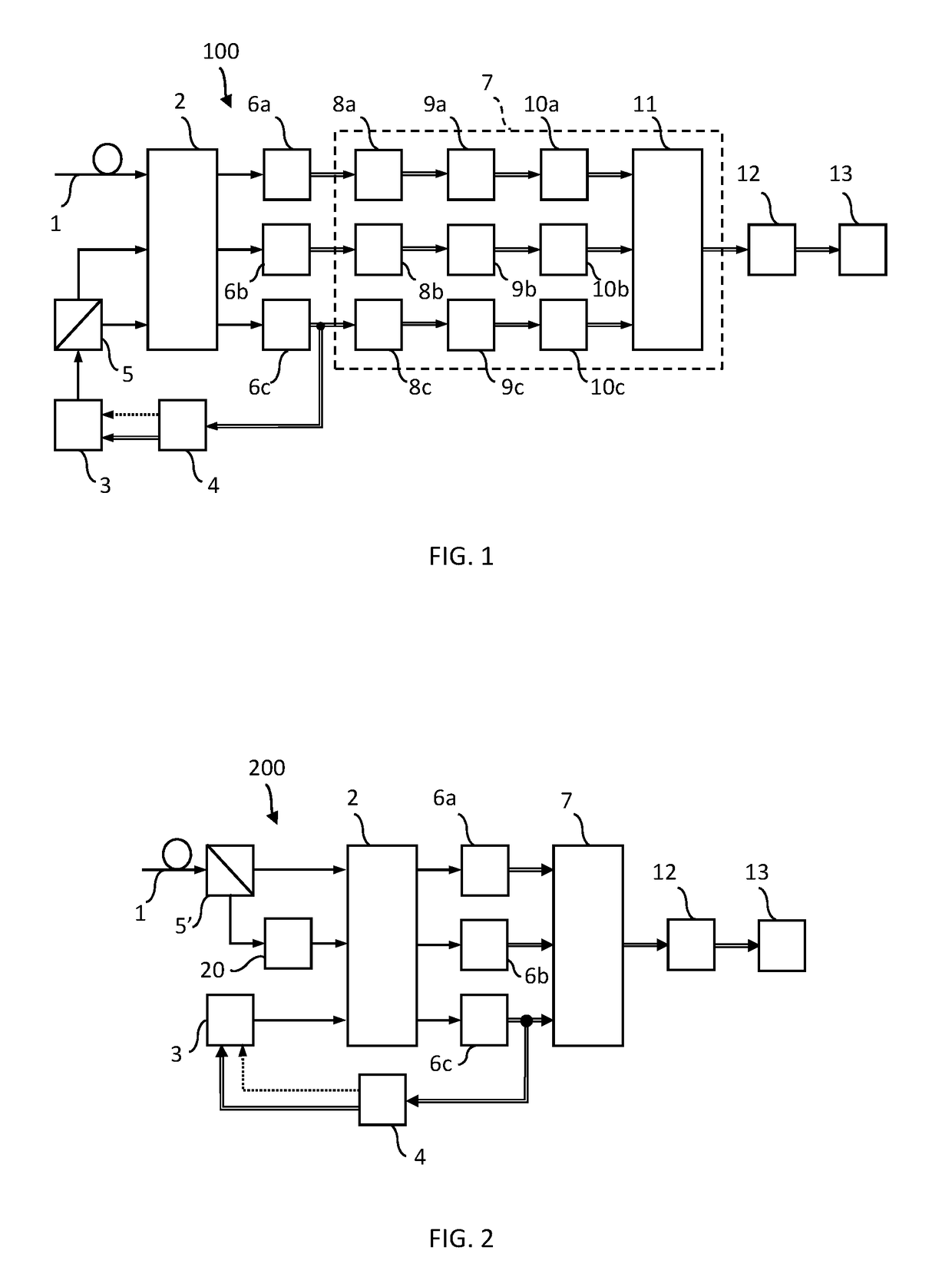
[0018]FIG. 2 is a block diagram of the invention;
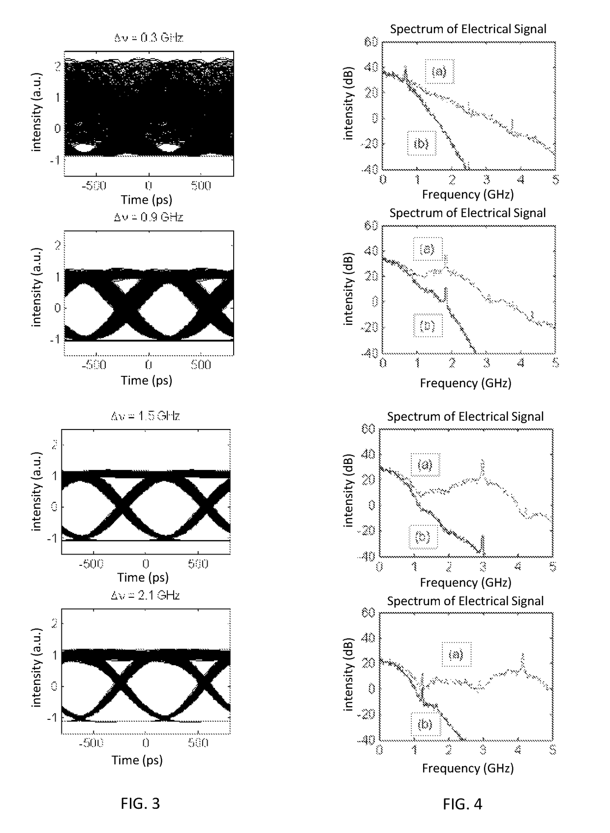
[0019]FIG. 3 shows eye diagrams of the demodulated signal obtained through simulations carried out for different values of the frequency difference between the received signal and the signal from the local oscillator; and
[0020]FIG. 4 shows the corresponding electrical spectra before and after low pass filtering.
Login to View More PUM
 Abstract
In a coherent optical receiver, a received signal and an oscillator-generated signal, having frequency difference such that the receiver operates under intradyne conditions, are made to beat in a 3×3 optical coupler. A polarizing beam-splitter splits one of the signals into components with orthogonal polarization which are applied to inputs of the coupler, which receives the other of the received or oscillator-generated signal. After photoelectric conversion, the signals are fed to analog processing devices generating an electrical signal representing the received signal that is fed to a low pass filter before being demodulated. The frequency difference between the signals and the passband of the filter are such that a component of the electrical signal, oscillating at a frequency depending on the frequency difference and having amplitude and phase depending on the instant state of polarization of the received signal, is suppressed. A method is also provided.
Description
TECHNICAL FIELD[0001]This invention relates to optical-fibre communication systems, and more particularly it concerns a coherent optical receiver which is independent of the state of polarisation of the received signal.BACKGROUND OF THE INVENTION[0002]Coherent techniques, thanks to their high wavelength selectivity and high sensitivity, are considered to be the most promising solution for detecting also ultra-dense wavelength division multiplexed optical signals, use of which is proposed for next generation access and distribution optical networks. In such an application, coherent receivers will have to be made available to the users, and therefore it is essential that they have a limited cost, typical of the products of consumer electronics. Yet, the currently existing coherent receivers, which have been studied for the transport network, employ sophisticated and hence expensive optical and electronic components, which are therefore incompatible with the requirements of a wide diff...
Claims
Login to View More Application Information
Patent Timeline
 Patent Type & Authority Patents(United States)
IPC IPC(8): H04B10/61
CPCH04B10/614H04B10/611H04B10/6166H04B10/65
Inventor CIARAMELLA, ERNESTOPRESI, MARCO
Owner TELEFON AB LM ERICSSON (PUBL)
Features
- R&D
- Intellectual Property
- Life Sciences
- Materials
- Tech Scout
- Unparalleled Data Quality
- Higher Quality Content
- 60% Fewer Hallucinations
Learn More Browse by: Latest US Patents, China's latest patents, Technical Efficacy Thesaurus, Application Domain, Technology Topic, Popular Technical Reports.
© 2025 PatSnap. All rights reserved.Legal|Privacy policy|Modern Slavery Act Transparency Statement|Sitemap|About US| Contact US: help@patsnap.com


