In situ membrane monitoring

a technology of in situ membrane and monitoring device, which is applied in the direction of membranes, instruments, material impedance, etc., can solve the problems of significant negative impact of reduction of membrane rejection characteristics, reducing salt rejection, and reducing membrane rejection characteristics. to achieve the effect of reducing precision

Inactive Publication Date: 2010-12-09
INPHAZE AUSTRALIA PTY LTD
View PDF8 Cites 12 Cited by
  • Summary
  • Abstract
  • Description
  • Claims
  • Application Information

AI Technical Summary

Benefits of technology

The patent text describes an alternative way to set electrodes in a membrane module to measure electrical properties. This involves placing the electrodes in two separate channels, which can be used for both two-terminal and four-terminal measurements. The advantage of this configuration is that it reduces voltage offsets that can occur when using different solutions for the electrodes, which can affect the accuracy of the measurements. The electrodes are connected to external electrode terminals, which allows for uninterrupted operation of the membrane module during the impedance measurements.

Problems solved by technology

The patent text discusses membrane separation systems and the factors that affect their performance, including pressure, concentration, cross flow velocity, and membrane material properties. The text also highlights the issue of fouling, which can lead to reduced permeate flux and lower quality permeate fluxes. The technical problem addressed by the patent is to provide a solution to effectively monitor and remedy fouling of membranes in membrane separation systems.

Method used


Image

  • In situ membrane monitoring
  • In situ membrane monitoring
  • In situ membrane monitoring

Examples


Embodiment Construction

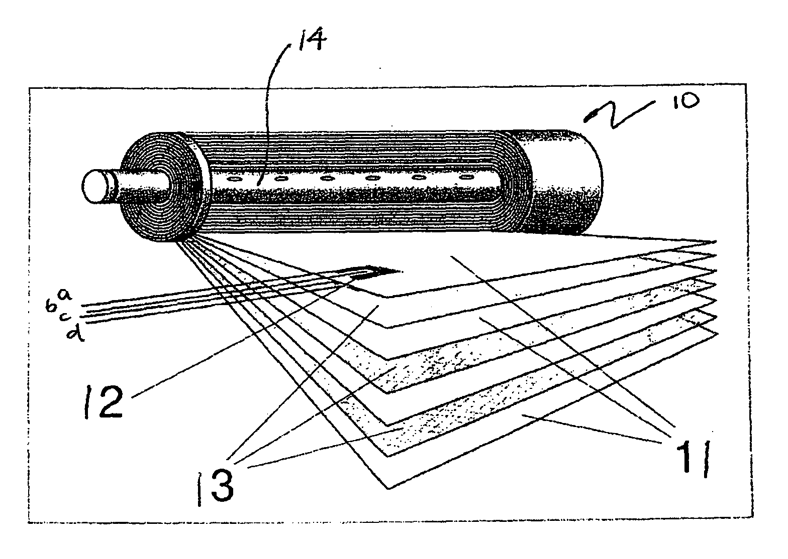
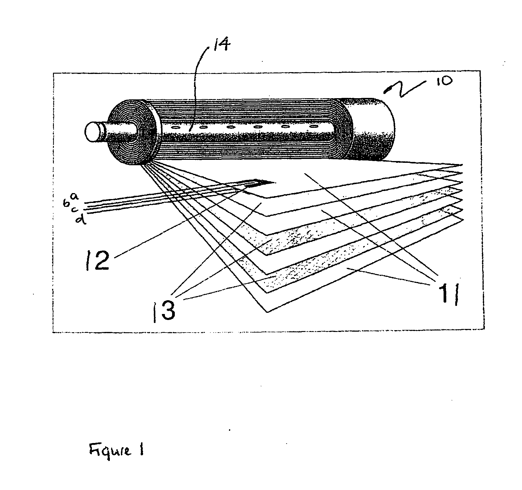
[0053]Referring to the drawings, FIG. 1 shows a “spiral wound” membrane separation module 10 including electrodes 12. In the drawing part of the module is shown “unwound” showing a cut-away view of the membranes 11 and spacers 13, as well as the electrodes 12 located within the spacers.

[0054]In operation, feed fluid is driven under pressure on one side of each membrane 11 whilst the permeate is collected from the other side. The permeate moves radially towards the centre of the module 10 along the spacer 13 between adjacent membranes 11 to a central permeate collection tube 14. The feed fluid moves between adjacent membranes, longitudinally along the module. This also provides a so called “crossflow” that assists in preventing fouling of the membranes. The spacers 13 are usually constructed from about 1 mm thick polymer threads made into a fabric. The spacers 13 provide a space between adjacent membranes in both the feed side and permeate side.

[0055]FIG. 1 shows a system with two pa...


PUM


Abstract

A method for in situ monitoring of a membrane of a membrane separation system comprises measuring a complex impedance of the membrane at a plurality of frequencies to provide an indication of the electrical conduction and electrical polarization properties of the membrane. The membrane based separation system for removing or reducing the concentration of materials carried in a fluid including a separation membrane has a first pair of electrodes separated by the membrane and arranged for measurement of the complex impedance of the membrane at a plurality of frequencies to provide the indication of the membrane properties. There may also be a second pair of electrodes separated by the membrane for injecting the stimulus current such that the injecting and monitoring functions are separated.

Description


Claims


Application Information

Patent Timeline
Owner INPHAZE AUSTRALIA PTY LTD
Why Eureka
Try Eureka