Bone Plate Assembly

Active Publication Date: 2010-12-09
VIANT AS&O HLDG LLC
View PDF9 Cites 41 Cited by
  • Summary
  • Abstract
  • Description
  • Claims
  • Application Information

AI Technical Summary

Benefits of technology

[0011]In that light, the present invention is directed to an orthopedic bone plate system comprising a compression screw, a locking screw, and a bone plate with a plurality of complex locking screw apertures. The inner wall of the bone plate is provided with a plurality of thread columns separated from each other by relief notches. Likewise, the head of the locking screw is provided with a plurality of thread columns separated from each other by relief notches. When the thread columns of one are aligned with the relief notches of the other, it is possible to impart a lateral force to the screw. This force causes the screw threads to jump eith

Problems solved by technology

This results in a desirable compression fit between

Method used


Image

  • Bone Plate Assembly
  • Bone Plate Assembly
  • Bone Plate Assembly

Examples


Embodiment Construction

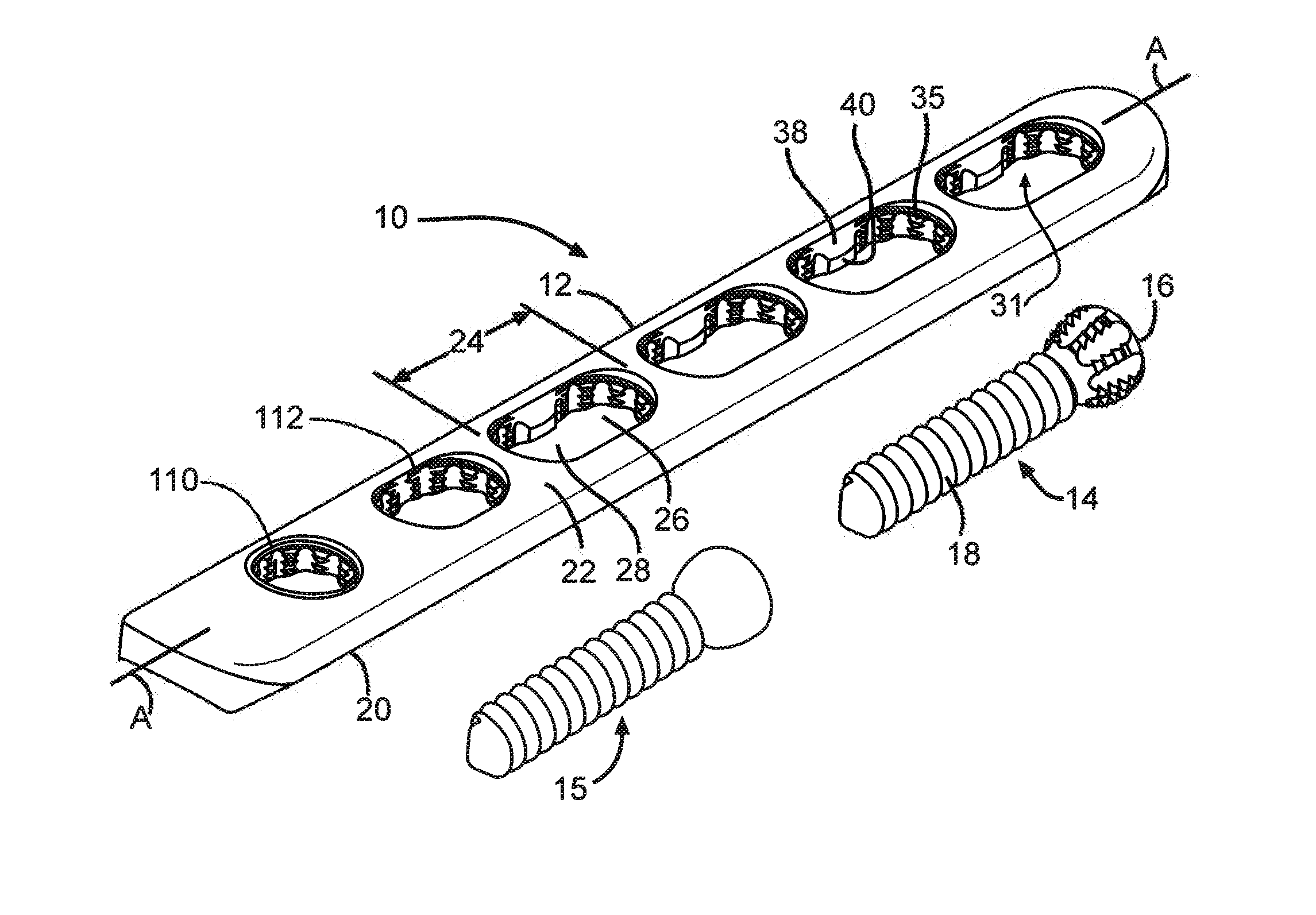
[0023]Turning now to the drawings, FIG. 1 is a perspective view of an orthopedic bone plate system 10 according to the present invention. The bone plate system 10 comprises a bone plate 12 and at least one locking screw 14. If desired, at least one compression screw 15 can also be included.

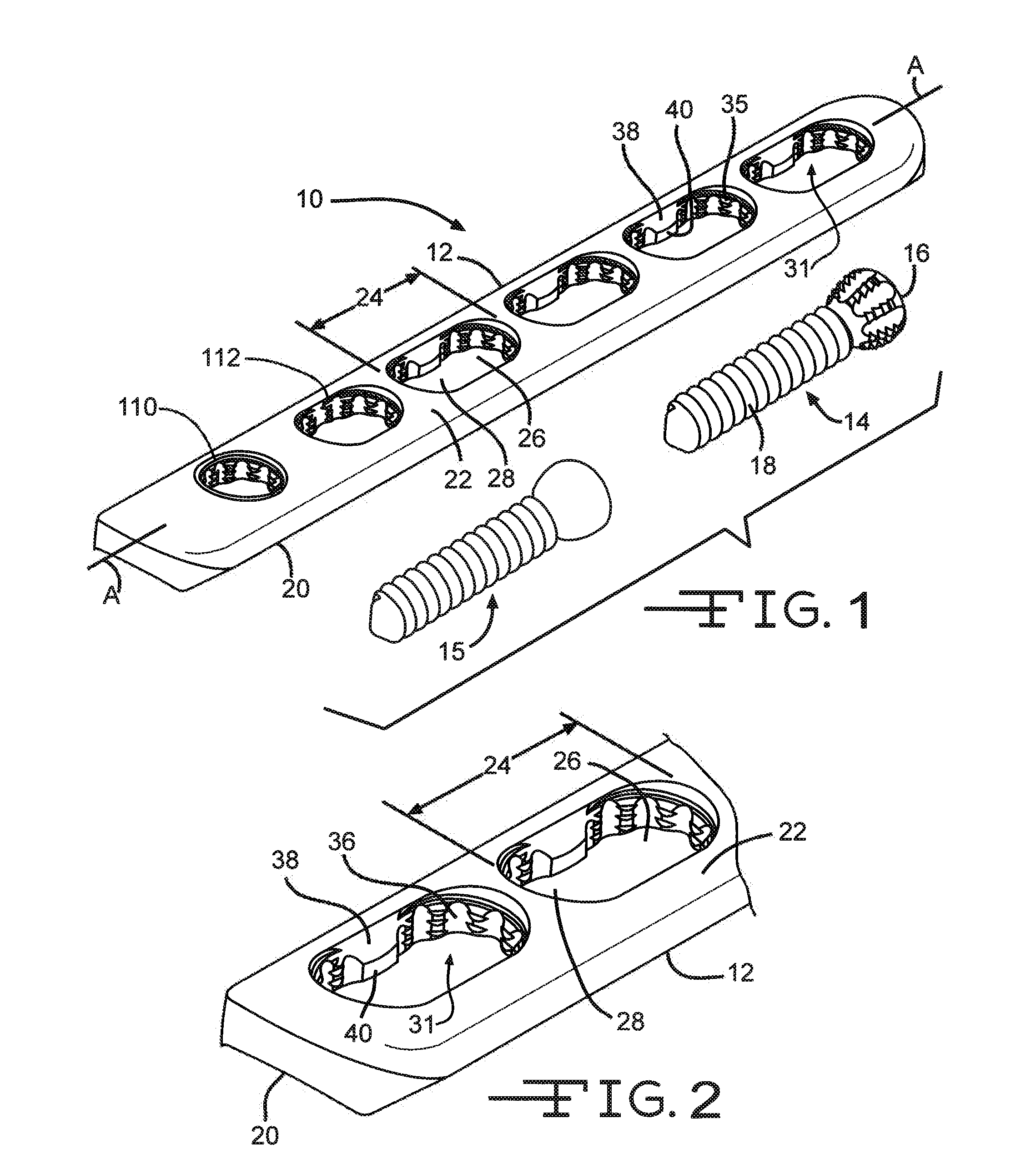
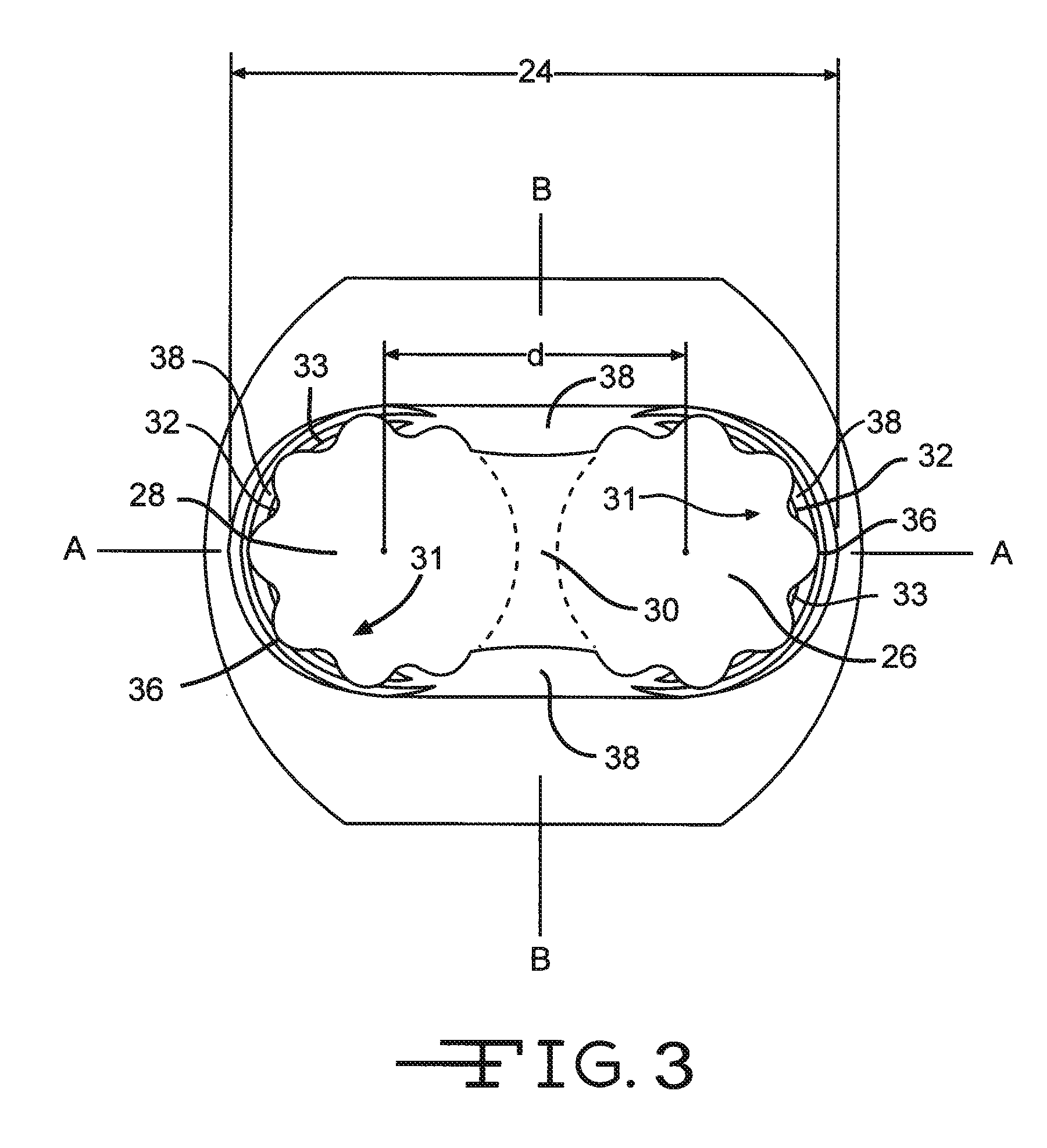
[0024]The bone plate 12 has a longitudinal axis A-A, an axis B-B (FIG. 3) which is oriented 90 degrees from axis A-A, a bone contacting bottom side 20 and a top side 22. At least one complex aperture 24 extends through the bone plate 12 from the top side 22 to the bottom side 20. The complex aperture 24 is designed to receive either the locking screw 14 or the compression screw 15. In this embodiment, the complex aperture 24 is comprised of at least one set of two immediately adjacent apertures 26, 28. The apertures 26, 28 do not overlap, thereby providing the complex aperture 24 as an oval shaped opening. FIG. 2 shows an enlarged perspective view of the complex aperture 24.

[0025]The plan view of ...


PUM


Abstract

The present invention relates to a bone plate designed to secure locking screws inserted into the plate at various angles. The interior wall surface of the plate apertures include a series of protruding threaded ridges interspaced by relief notches. The threaded ridges and intermediate relief notches of the bone plate in combination with the threaded ridges and intermediate relief notches of the locking screw head allow the locking screw to bypass or “lump” threads of the bone plate. Thus, the locking screw can be inserted into the bone plate at a first angle and part-way through its advancement along the threads of the bone plate that angle can be changed. The second angle can either be greater than the first with respect to an orientation perpendicular to a longitudinal axis of the bone plate, or less than. This gives the physician a great amount of flexibility during a surgical procedure.

Description

CROSS-REFERENCE TO RELATED APPLICATION[0001]The present application also claims priority from U.S. Provisional Application Ser. No. 61 / 175,855, filed May 6, 2009.BACKGROUND OF THE INVENTION[0002]1. Field of the Invention[0003]The present invention is related generally to implantable orthopedic implants. More specifically, the present invention is related to implantable orthopedic bone plates used to reinforce fractured bones.[0004]2. Background of the Invention[0005]Orthopedic bone plates play a critical role in the healing process of broken bones. Once a bone has been fragmented, it is ideal for the broken bone fragments to be joined back together under compression to promote improved healing. The bone plate is a critical device that is used as a stabilizing bar to bridge the gap between bone fragments.[0006]During surgery, a bone plate is inserted next to the fragmented bone of a patient. Compression screws are first placed through the bone plate. They are anchored into each of th...

Claims


Application Information

Patent Timeline
IPC IPC(8): A61B17/80
CPCA61B17/8057A61B17/8605
Inventor WHITE, PATRICK M.CHENAUX, FABRICEMERETTE, JEAN-SEBASTIEN
Owner VIANT AS&O HLDG LLC
Why Eureka
Try Eureka