
Turntable and method for manufacturing the same

Inactive Publication Date: 2010-12-09
NIDEC CORP
View PDF18 Cites 8 Cited by
  • Summary
  • Abstract
  • Description
  • Claims
  • Application Information

AI Technical Summary

Benefits of technology

[0007]In order to overcome the problems described above, the present invention reliably prevents sinkage of a resin of a central resin member, particularly at a disk guide portion thereof.

Problems solved by technology

In case of a structure in which the upper and lower surfaces of the rotor yoke are covered with a resin, it is likely that deformation such as sinkage occurs on the surface of the resin member in an injection molding process.

Method used


Image

  • Turntable and method for manufacturing the same
  • Turntable and method for manufacturing the same
  • Turntable and method for manufacturing the same

Examples


Embodiment Construction

[0030]In the subject specification, the upper side in the direction of a center axis J1 is referred to as “upper” and the lower side as “lower”. The terms “upper”, “lower”, “left” and “right” used in describing the respective members are intended to designate the positional relationship or direction in the drawings and not to designate the positional relationship or direction when actually mounted to devices.

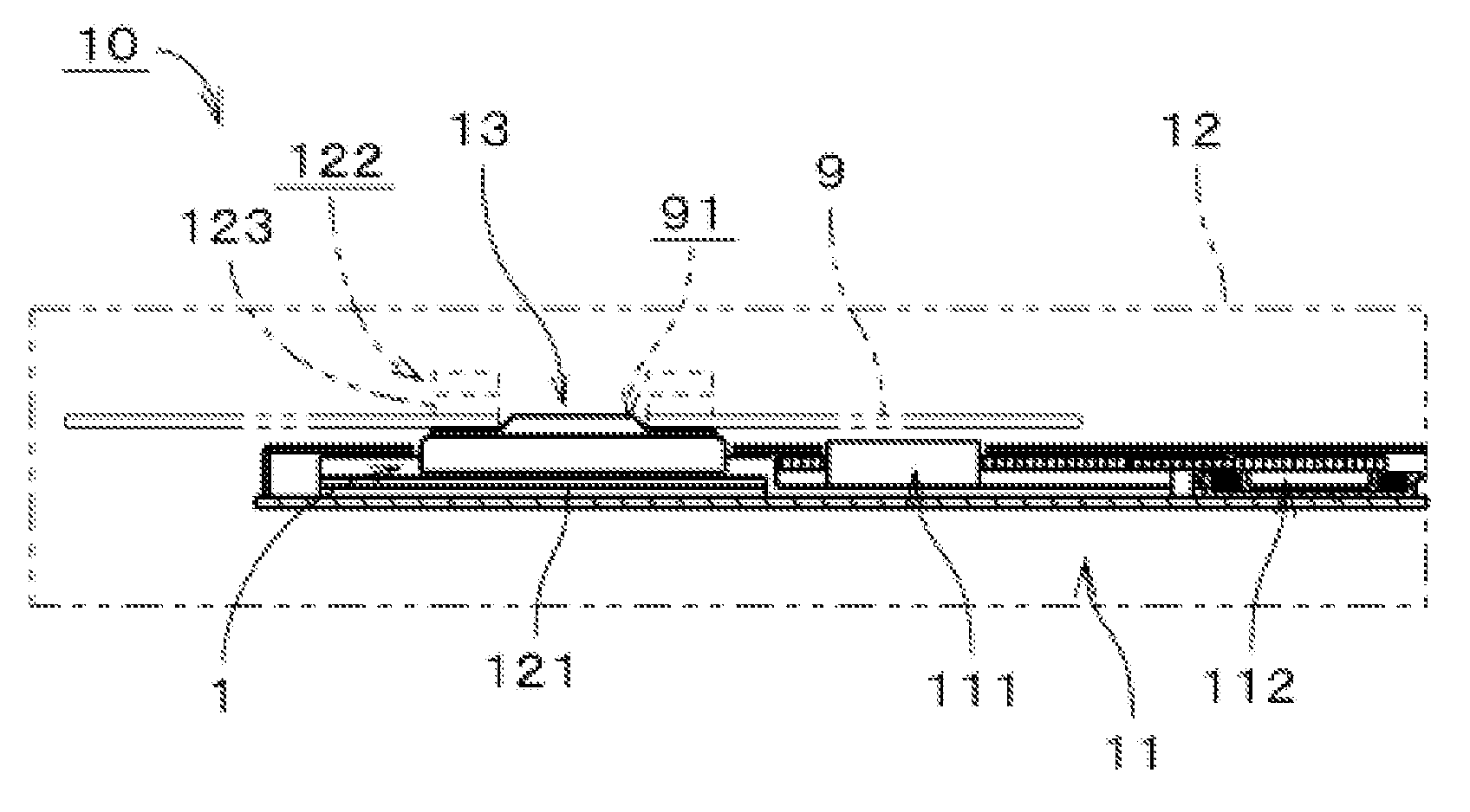
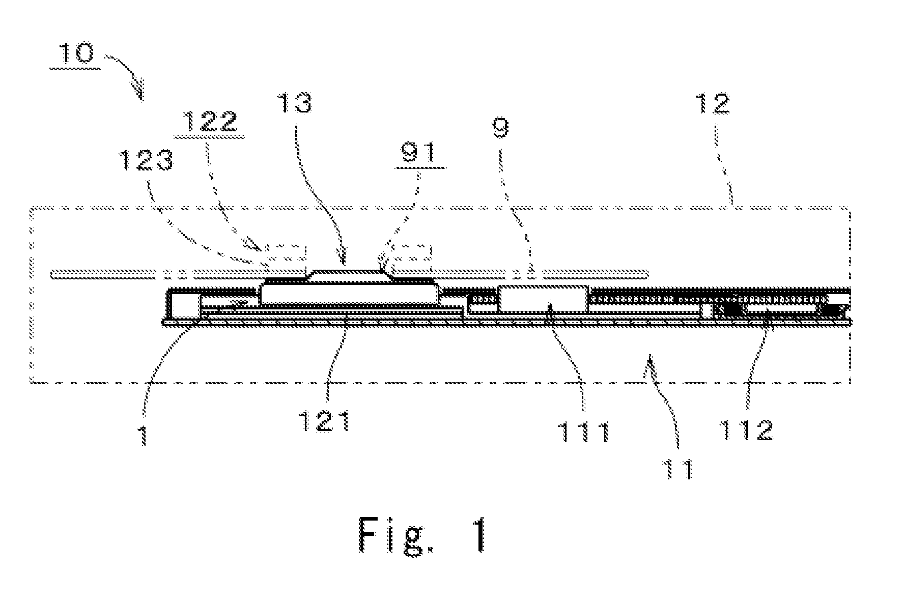
[0031]FIG. 1 is a sectional view showing a storage disk drive apparatus 10 provided with a motor according to a first embodiment of the present invention, which view is taken along a plane containing the center axis of the storage disk drive apparatus 10. As shown, the storage disk drive apparatus 10 can include a motor 1, an access unit 11 and a box-like housing 12 arranged to accommodate the motor 1 and the access unit 11 therein. In FIG. 1, the housing 12, a clamper 122, a clamp magnet 123 and a storage disk 9 are indicated by double-dot chain lines. The motor 1 can be held i...


PUM


Abstract

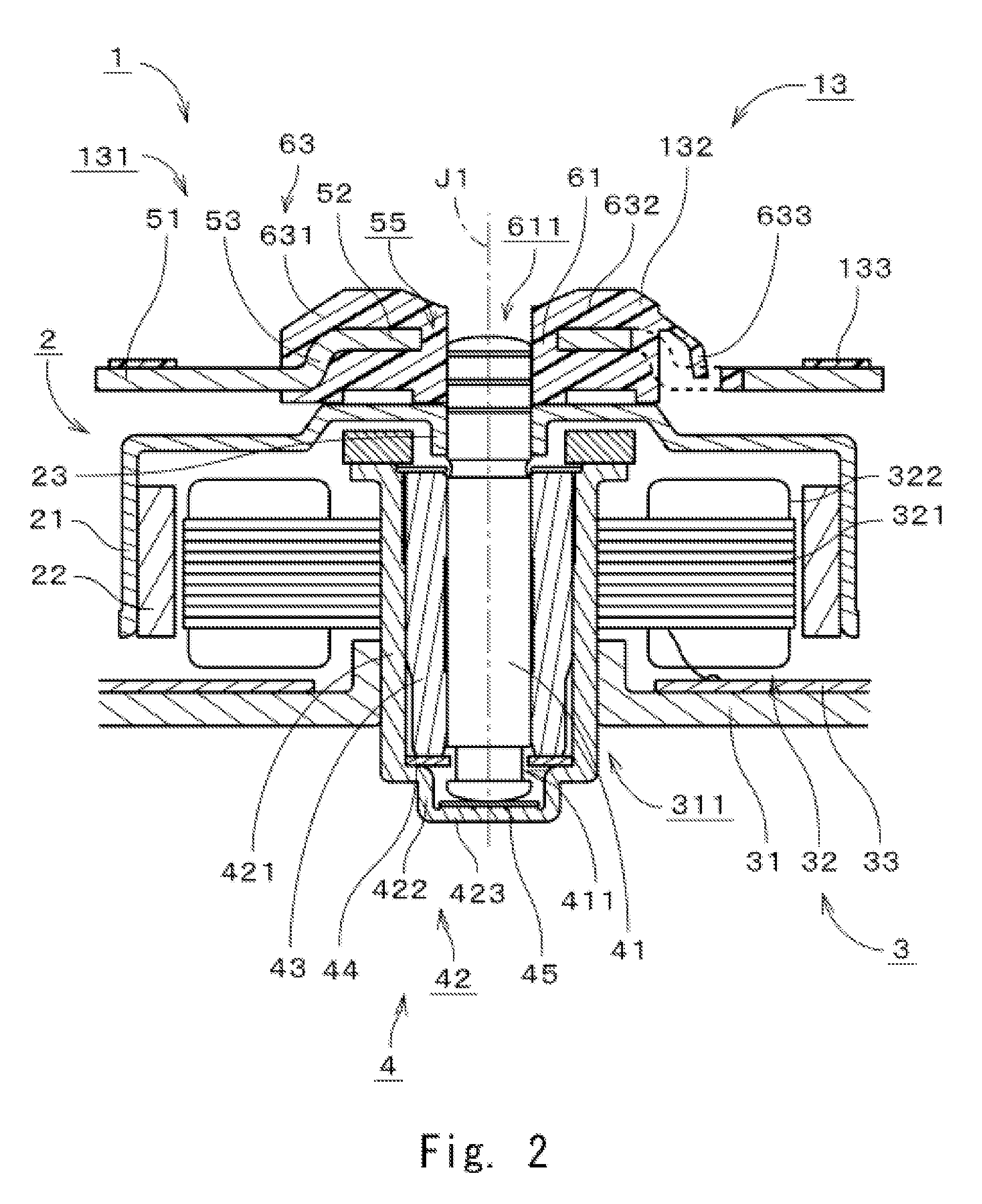
A turntable for a storage disk drive apparatus includes a plate member made of a ferromagnetic material and a central resin member arranged at the center of the plate member and formed into a single member by injection-molding a resin. The plate member includes a peripheral plate portion and a central plate portion positioned higher than the peripheral plate portion. The central plate portion includes a plate center hole defined at the center of the plate member. The central resin member includes a resinous cylinder portion extending through the plate center hole and defining a resin central through-hole, a disk guide portion arranged to guide a disk center hole, and a resinous connector portion arranged above the central plate portion to interconnect the resinous cylinder portion and the disk guide portion.

Description

BACKGROUND OF THE INVENTION[0001]1. Field of the Invention[0002]The present invention relates to a storage disk turntable, a motor and a storage disk drive apparatus.[0003]2. Description of the Related Art[0004]In a conventional storage disk drive apparatus, a motor is provided with a turntable for holding a storage disk. The turntable includes a turntable body and a center spindle. The turntable body is made of a magnetic material. The center spindle is made of a resin integrally formed with the turntable body.[0005]In case of a structure in which the upper and lower surfaces of the rotor yoke are covered with a resin, it is likely that deformation such as sinkage occurs on the surface of the resin member in an injection molding process. It is also likely that a weld line is generated in the portion where a resin is finally filled. In the upper outer periphery of the resin member, there is provided an outer circumferential portion which is to be fitted to the center hole of a stora...

Claims


Application Information

Patent Timeline
IPC IPC(8): G11B17/028B29C45/14
CPCG11B17/0282G11B19/2009
Inventor NAKANISHI, KOSUKETABATA, SHINYASONODA, TOSHIHIDEKITAMURA, YOSHIHISA
Owner NIDEC CORP
Learn More