Eureka AIR delivers breakthrough ideas for toughest innovation challenges, trusted by R&D personnel around the world.

Adjustable after-market sash window stop

Active Publication Date: 2010-12-16
VISION INDS GROUP
View PDF10 Cites 10 Cited by
  • Summary
  • Abstract
  • Description
  • Claims
  • Application Information

AI Technical Summary

Benefits of technology

[0007]It is an object of the invention to provide a means of preventing accidental egress of a child out of a sliding sash window or sash door.
[0010]It is a further object of the invention to provide a sliding sash window stop that may be easily installed onto a window that is already in use in a building.
[0012]It is also an object of the invention to provide a means of quickly adjusting the stop to accommodate different depths of sash window insets within a master window frame.
[0014]The after-market safety stop disclosed herein is intended for attachment to a master frame of a sliding sash window assembly or a sliding sash door assembly, to be capable of limiting sash travel between a closed position and a safe position, where the safe position is a sash position between the closed sash position and a full-open sash position. The safe position may be established to permit sash movement sufficient for ventilation, but be small enough to prevent window sash travel of a magnitude that would allow a small child to accidentally fall out of the opened window. The safety stop may be attached to older windows already installed in a building, because they lack such a stop, or even where they have a safety stop, but it permits travel that is excessive or insufficient in comparison with the needs of the occupant.

Problems solved by technology

The safety stop may be attached to older windows already installed in a building, because they lack such a stop, or even where they have a safety stop, but it permits travel that is excessive or insufficient in comparison with the needs of the occupant.

Method used


Image

  • Adjustable after-market sash window stop
  • Adjustable after-market sash window stop
  • Adjustable after-market sash window stop

Examples


Embodiment Construction

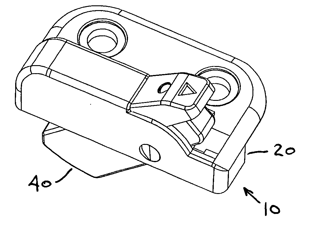
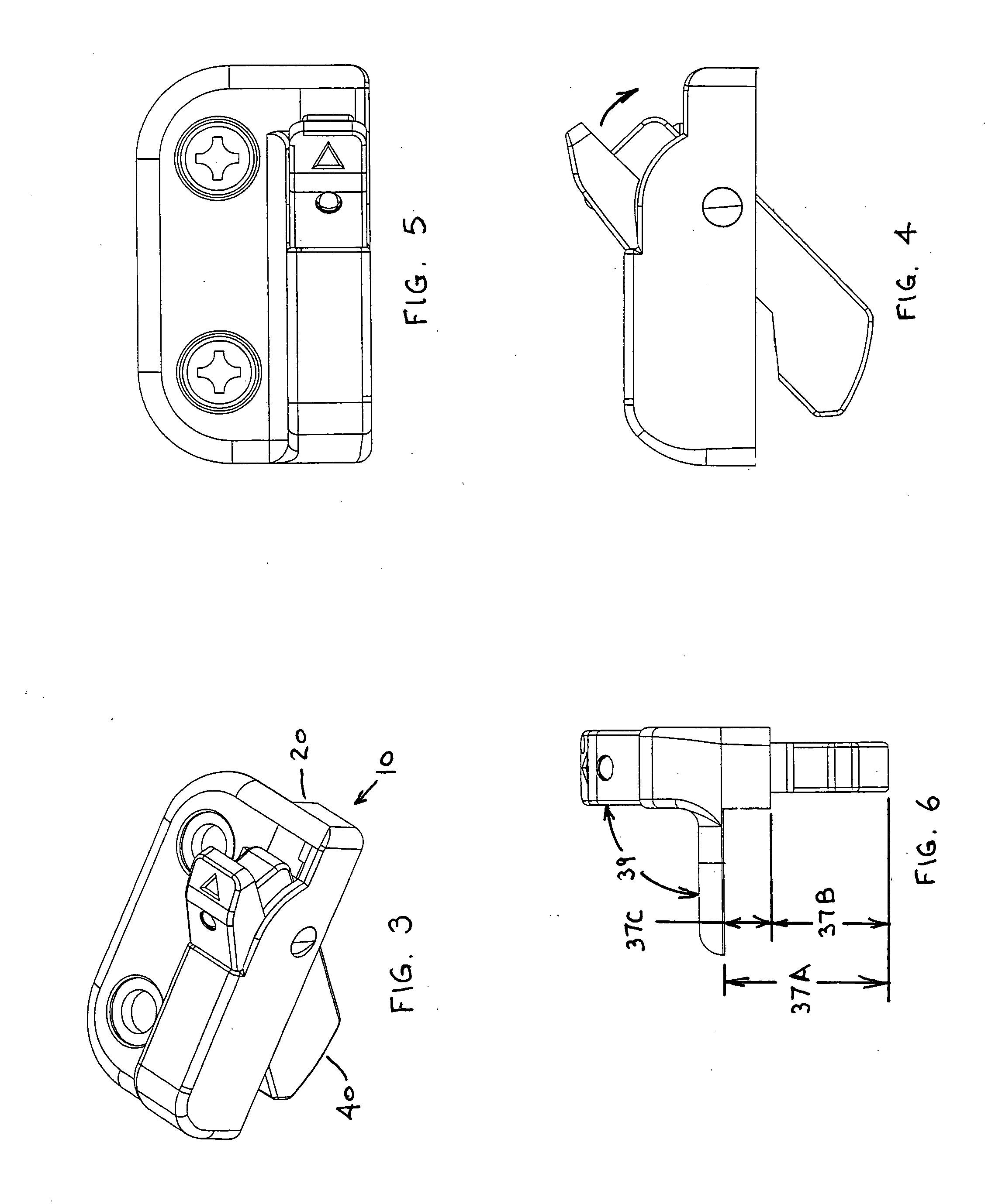
[0053]FIG. 5 shows a first embodiment of the adjustable window stop assembly 10 of the present invention, which may be practiced using the adjustable window stop assembly 10 and one or more spacer blocks (80A, 80B, etc) of the same or of varying thickness.

[0054]The window stop assembly 10 may include a housing 20, a tumbler 40, and a biasing member 60, as seen in FIG. 20, the operation of which is disclosed by U.S. patent application Ser. No. 12 / 456,347, which claims priority on U.S. Provisional Application Ser. No. 61 / 217,365, filed May 29, 2009, the disclosures of each being incorporated herein by reference. The housing 20 may be constructed to be of many different shapes, and need not resemble the box-like structure of the housing shown in FIGS. 12A through 12E. In fact, the housing could be formed of a single walled member and could resemble half of an egg-shape. It may be formed as one continuous piece, as with a casting or an injection molded plastic part, or it may be an asse...


PUM

PropertyMeasurementUnit
Thicknessaaaaaaaaaa
Forceaaaaaaaaaa
Angleaaaaaaaaaa

Abstract

An adjustable stop is adapted to limit travel of a sliding sash window / door, and can be installed upon the window / door master frame during initial manufacturing of the product, or may be an after-market option added at some time after manufacturing was completed. The stop may even be installed upon sash windows / doors currently in service in a building. The stop is intended to limit sash travel between a closed position and a safe position, where the safe position is a position significantly less than a full-open position. The safety stop may be comprised of a housing and a tumbler being pivotally mounted within a cavity in the housing, with a spring to bias the tumbler out of an opening in the housing. Mounting is by a flange extending from the housing, with spacers of varying thickness that are capable of removably attaching thereon to accommodate sash to master frame height differences.

Description

CROSS REFERENCES TO RELATED APPLICATIONS[0001]This application is a continuation-in-part of U.S. patent application Ser. No. 12 / 456,347, titled “Single Action Vent Stop,” filed Jun. 15, 2009, which claims priority on U.S. Provisional Application Ser. No. 61 / 217,365, filed May 29, 2009, the disclosures of which are hereby incorporated by reference.FIELD OF THE INVENTION[0002]The present invention relates to improvements in safety latches for sliding sash windows and doors, and more particularly to a safety latch which permits after-market installation on a variety of different window configurations, and is capable of preventing accidental egress of a small child from a window.BACKGROUND OF THE INVENTION[0003]A sash window or sash door is comprised of a master frame that permits installation into a wall of a home or other building. The master frame is generally arranged to receive at least one sliding member, with the sliding member being in the form of a window or door member that is...

Claims


Application Information

Patent Timeline
IPC IPC(8): E05C3/14E05C3/12E06B3/44B23Q17/00
CPCE05B63/0056E05B65/0847E05C3/14E05C17/60E05C2007/007Y10T292/42Y10T292/1075Y10T292/1052Y10T29/49778
Inventor LIANG, LUKECHEN, DAVID
Owner VISION INDS GROUP
Why Eureka
Eureka Blog
Learn More