Electrolytic hydrogen generating system

a hydrogen generating system and electrolysis technology, applied in the direction of electrochemical machining apparatus, metal-working apparatus, machines/engines, etc., can solve the problems of insufficient supply of gas at acceptable temperatures, unsatisfactory hydrogen generating system that efficiently

Inactive Publication Date: 2010-12-16
ETORUS
View PDF46 Cites 1 Cited by
  • Summary
  • Abstract
  • Description
  • Claims
  • Application Information

AI Technical Summary

Benefits of technology

[0065]One advantage of some embodiments of this disclosure is that each electrode plate can be monitored to control an amperage level generated. As described in detail below, power can be channeled to each electrode plate as needed to increase hydrogen production for a given amperage. This can increase the generation of hydrogen and oxygen available at start-up and significantly reduce a usual warm-up period required to get the hydrogen generating system 11 to full production at optimum temperature.

Problems solved by technology

However, a satisfactory hydrogen generating system that efficiently uses the power supplied to the system and generates a sufficient supply of gases at acceptable temperatures does not yet exist.

Method used


Image

  • Electrolytic hydrogen generating system
  • Electrolytic hydrogen generating system
  • Electrolytic hydrogen generating system

Examples


Embodiment Construction

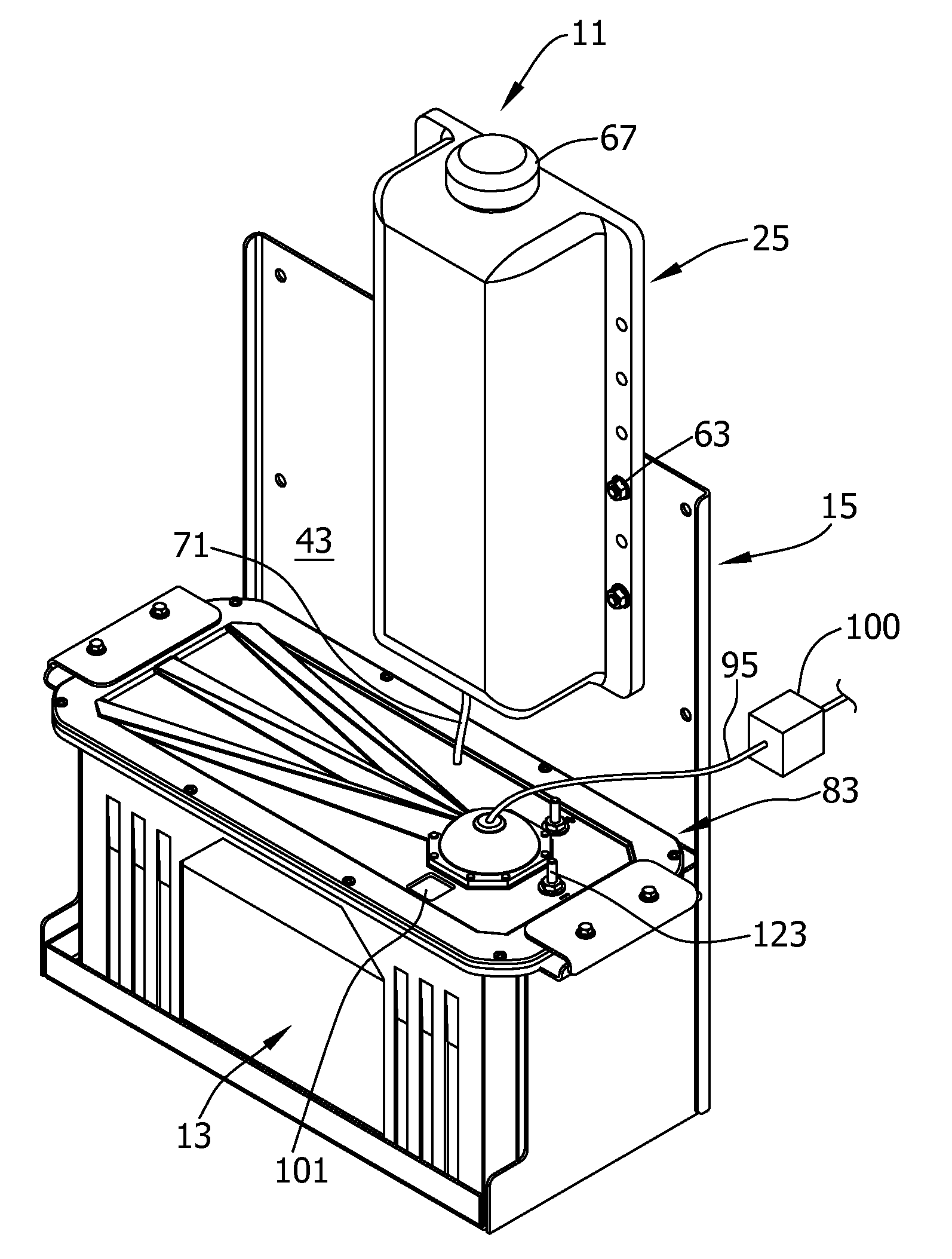
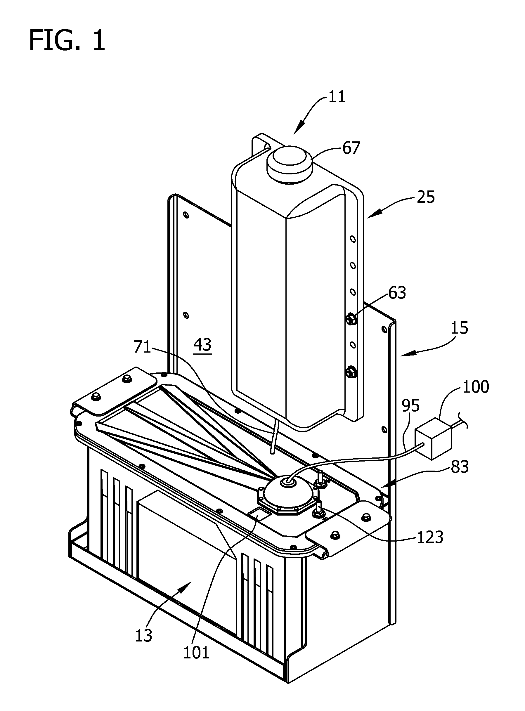
[0039]Referring now to the drawings and particularly to FIG. 1, a fuel emission device or hydrogen generating system of one suitable embodiment is generally designated 11. The hydrogen generating system 11 generally comprises a housing 13 and a frame 15 for supporting the housing 13. In this embodiment, the hydrogen generating system 11, and in particular the housing 13 and the frame 15, are adapted for mounting on a vehicle 19 (see FIG. 18), such as a diesel tractor of a tractor-trailer combination, and operably connected to an internal combustion engine 21 (see FIG. 18). A power source of the hydrogen generating system 11 may be, for example a 12 volt or a 24 volt source, though the hydrogen generating system 11 may be adapted to multiple voltage sources. This embodiment also includes a reservoir 25 containing maintenance solution 27, as shown in FIG. 5, for facilitating continued operation of the hydrogen generating system 11. The reservoir 25 may, however, be omitted within the ...


PUM

PropertyMeasurementUnit
voltageaaaaaaaaaa
voltageaaaaaaaaaa
temperaturesaaaaaaaaaa

Abstract

A hydrogen generating system includes an electrode plate assembly including a plurality of electrode plates, a first connector and a second connector, each connector connected to at least some of the plates, an amperage sensor, a temperature sensor, and a controller capable of receiving signals from the amperage sensor and temperature sensor to monitor an amperage and a temperature of the hydrogen generating system. The controller includes a processor programmed to receive a target amperage, select, based on the target amperage, certain of the plurality of conductive plates to receive voltage input during a predetermined duty cycle, determine an actual amperage and an actual temperature resulting from the voltage input, compare the actual amperage and the actual temperature to a respective amperage threshold and temperature threshold; and adjust the duty cycle for applying voltage based on the comparison.

Description

CROSS REFERENCE TO RELATED APPLICATIONS[0001]This application claims the benefit of U.S. Provisional Patent Application No. 61 / 115,463 filed on Nov. 17, 2008 and 61 / 117,481 filed on Nov. 24, 2008, respectively, both of which are hereby incorporated by reference in their entirety.BACKGROUND[0002]The use of hydrogen and oxygen gas to supplement the conventional fuel in an internal combustion engine in order to increase the efficiency of the engine is known. For example, electrolytic hydrogen generating systems are known to produce hydrogen and oxygen gases for use as fuel additives. However, a satisfactory hydrogen generating system that efficiently uses the power supplied to the system and generates a sufficient supply of gases at acceptable temperatures does not yet exist.BRIEF DESCRIPTION[0003]In one aspect, a hydrogen generating system includes an electrode plate assembly including a plurality of electrode plates, a first connector and a second connector, each connector connected ...

Claims


Application Information

Patent Timeline
Patent Type & Authority Applications(United States)
IPC IPC(8): C25B1/02C25B9/04C25B15/02
CPCC25B1/06C25B9/063C25B11/03F02M25/12Y02E60/366Y02T10/121Y02E60/36Y02T10/12C25B1/04C25B11/00C25B11/036
Inventor ARNETT, LESLIE PAULDEHART, SCOTT ALANYELIN, ROBERT E.
Owner ETORUS
Why Eureka
Try Eureka