Fuel Cell Device

a fuel cell and cell technology, applied in the direction of fuel cells, electrochemical generators, electrical equipment, etc., can solve the problems of affecting the inability to establish distribution channels for methanol, and the near-capacity limit of hydrogen generating components, so as to improve the efficiency of electric power generation, enhance the hydrogen generation at the hydrogen generating member, and suppress the energy consumption at the heating section

Inactive Publication Date: 2013-03-14
KONICA MINOLTA INC
View PDF4 Cites 1 Cited by
  • Summary
  • Abstract
  • Description
  • Claims
  • Application Information

AI Technical Summary

Benefits of technology

[0013]According to the present invention, the hydrogen generating member can be heated, and thus hydrogen generation at the hydrogen generating member can be enhanced. Furthermore, according to the present invention, when the temperature of the hydrogen generating member is not less than a predetermined temperature, an operation by the heating section that heats the hydrogen generating member is halted, and thus energy consumption at the heating section can be suppressed. This provides improved electric power generation efficiency.

Problems solved by technology

These types of batteries, however, have almost reached their capacity limits to such an extent that a significant increase in their capacities can no longer be expected.
Furthermore, even in a case where methanol, which is relatively easily available, is used as a fuel, there is a problem that it would take years to establish distribution channels for methanol.

Method used


Image

  • Fuel Cell Device
  • Fuel Cell Device
  • Fuel Cell Device

Examples


Embodiment Construction

[0018]The following describes an embodiment of present invention with reference to the appended drawings. The present invention, however, is not limited to the embodiment described below.

Schematic Configuration of Fuel Cell Device According to One Embodiment of Present Invention

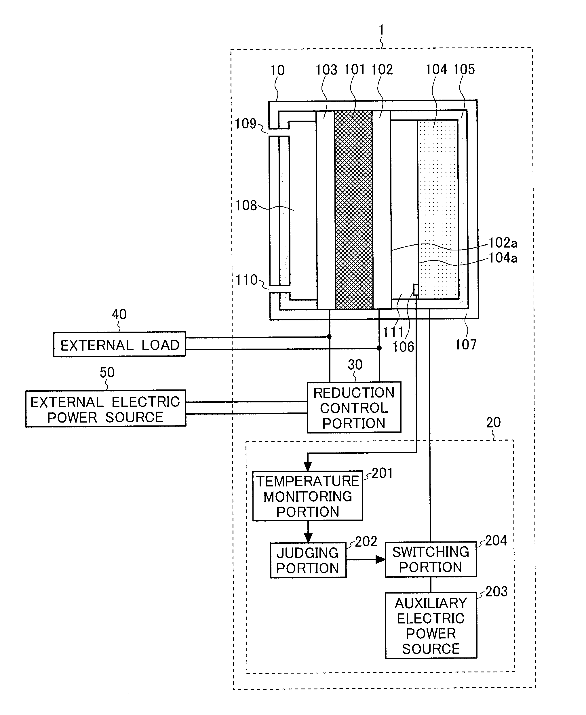
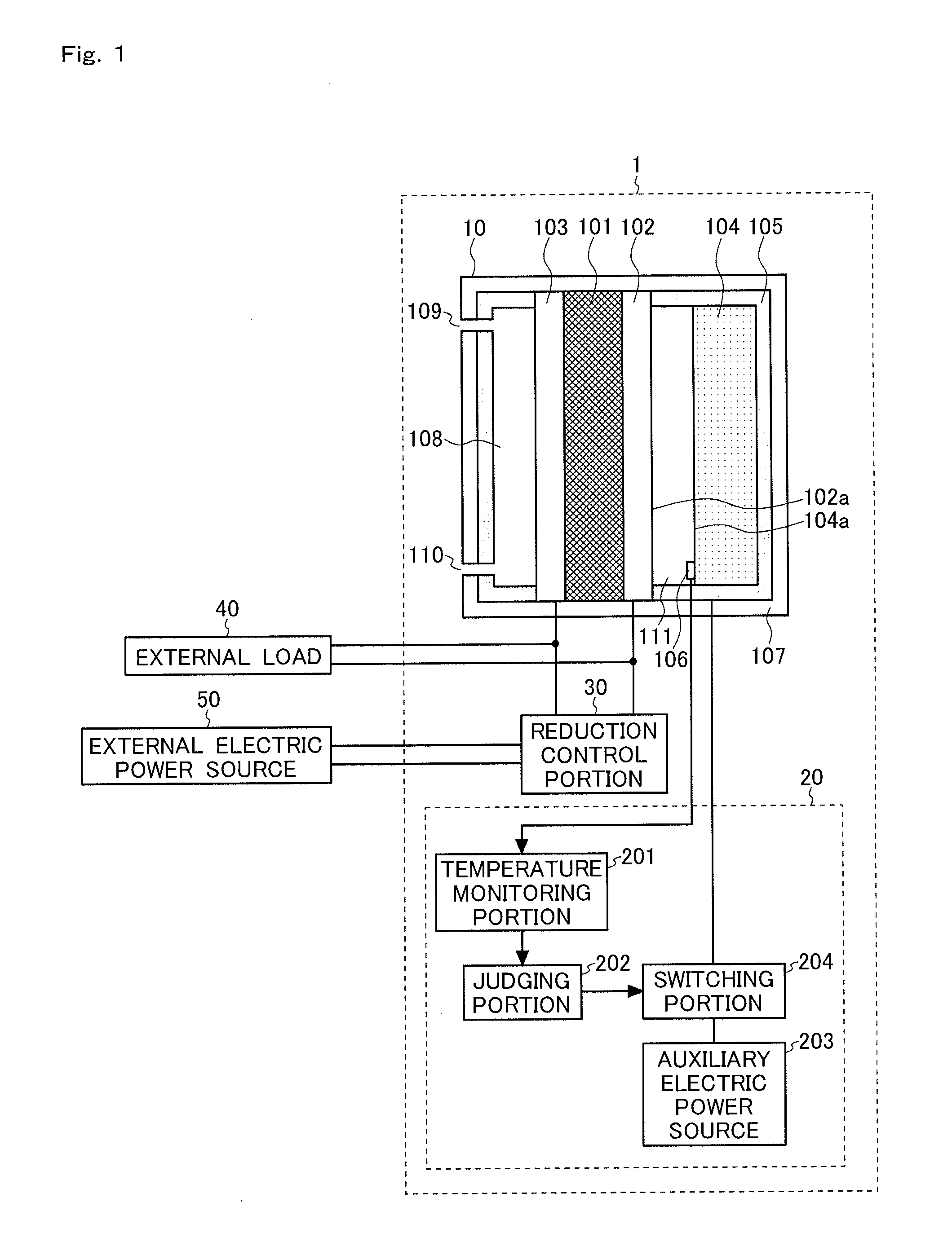
[0019]First, with reference to FIG. 1, a description is made of a schematic configuration of a fuel cell device according to one embodiment of the present invention. FIG. 1 is a schematic diagram showing the schematic configuration of the fuel cell device according to the one embodiment of the present invention.

[0020]A fuel cell device 1 according to the one embodiment of the present invention includes, as shown in FIG. 1, a fuel cell main body 10 and a temperature control unit 20. In FIG. 1, the fuel cell main body 10 is shown in the form of a sectional schematic diagram, and the temperature control unit 20 is shown in the form of a block diagram.

[0021]The fuel cell main body 10 has an electrolyte membrane ...


PUM

PropertyMeasurementUnit
temperature Tpaaaaaaaaaa
temperatureaaaaaaaaaa
timeaaaaaaaaaa

Abstract

The fuel cell device is provided with: an electricity-generating unit having a fuel electrode (102), an air electrode (103), and an electrolyte film (101) sandwiched between the fuel electrode (102) and the air electrode (103); a hydrogen-generating member (104) that, by means of an oxidation reaction with water, generates hydrogen for supplying to the fuel electrode (102) of the aforementioned electricity-generating unit; a heater (105) that heats the hydrogen-generating member (104); a temperature sensor (106) that detects the temperature of the hydrogen-generating member (104); and a temperature control unit (20) that controls the temperature of the hydrogen-generating member (104) in response to the detection results of the temperature sensor (106). The temperature control unit (20) stops the passage of electricity through the heater (105) when it has been determined that the temperature of the hydrogen-generating member (104) is at least a predetermined temperature.

Description

TECHNICAL FIELD[0001]The present invention relates to a fuel cell device, and particularly to a fuel cell device having a hydrogen generating member.BACKGROUND ART[0002]In recent years, along with improvements in functionality and performance of portable electronic equipment such as a cellular phone, a portable information terminal, a notebook-sized personal computer, a portable audio device, a portable visual device, and so on, there has been a growing demand that battery cells for driving them have an increased capacity. As battery cells for driving such portable electronic equipment, conventionally used are a lithium battery and a nickel-cadmium battery. These types of batteries, however, have almost reached their capacity limits to such an extent that a significant increase in their capacities can no longer be expected. With this as a background, in place of a lithium battery and a nickel-cadmium battery, a fuel cell that has a high energy density and can achieve a capacity incr...

Claims


Application Information

Patent Timeline
Patent Type & Authority Applications(United States)
IPC IPC(8): H01M8/06
CPCH01M8/1206Y02E60/525H01M2008/1293Y02E60/528H01M8/04373H01M8/04738H01M8/186H01M8/065H01M8/1231Y02E60/50
Inventor URATANI, SHOICHIWADA, SHIGERUUEYAMA, MASAYUKIISHIDA, NOBUHISA
Owner KONICA MINOLTA INC
Why Eureka
Try Eureka